TU-4

The Tektronix TU-4 is a plug-in for testing 560-series oscilloscope mainframes including the Type 506 as well as the Type 129 four bay plugin enclosure and power supply. It contains load resistors for testing the power supplies of the scope. These apply lighter loads to the early 560, low power scopes, and heavier loads to the later 561 and other higher power scopes in the 560 family. For full load testing, two TU-4 units are necessary, and, presumably four for a Type 129.
There are two neon lamps on the TU-4 front panel that are intended to show whether the AC line input power of the scope under test is connected correctly. The functioning of these lamps depends on 117 VAC hot and neutral being connected to pins 7 & 8, respectively, in the plugin connectors of the scope being tested. This will work correctly even if the scope being tested is wired for 234 VAC. These pins were not connected in later models of the 560 series. Consequently, the neon lamps are non-functional when the TU-4 is used with a 561B, a 564B, or a 568 (SN 288 or later.)
When the TU-4 is properly calibrated, the RIPPLE AND PERCENT DC ERROR connector output delivers 10 mV for each 1% error of the the power supply in the scope. This output has a 1 MΩ source impedance and is designed to drive a 1 MΩ scope input. Thus, monitoring this voltage using a modern DVM will exaggerate any error by a factor of about 1.8. There is a button to filter the ripple from this output, and another button to ground the output, to provide an accurate ground reference. While development of the TU-4 was stopped rather early, due to the difficulty of getting it to work correctly with all the members of the 560 family, it remains useful for doing quick checks of voltage and ripple.
The SIGNAL INPUT connector drives the vertical deflection plates directly, with no amplification. Connecting a 20 V calibrator signal to this input should produce a square wave trace. If this calibrator signal is also connected to the Z AXIS INPUT, this should reduce the intensity of the leading edge of the square wave.
Moving the toggle switch to the DUAL TRACE position should produce two traces about two major divisions apart.
Note that some of the photos on this page show a TU-4 with BNC connectors instead of UHF connectors. That was a change that was scheduled to start at SN 300, but production ended before this upgrade could be implemented. The UHF connectors, but not the binding post, were scheduled for that change. While the BNC connectors are a welcome improvement, the TU-4 with BNCs shown on this page must have been upgraded after it was sold.
Pictures
-
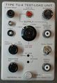
Front w/UHF connectors
-
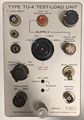
Front w/BNCs
-
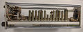
Left
-
Left
-
Right
-
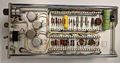
Top
-
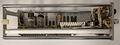
Bottom


