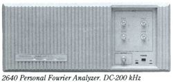
2640
The Tektronix 2640 is a Fourier analyzer that links dedicated signal acquisition and analysis with a personal computer’s mass storage and graphics. It allows measurement solutions for electrical, mechanical, and electromechanical applications in the DC to 200 kHz frequency range. Typical applications are Structural Analysis, Control Systems, Machine Vibration, Audio and Acoustic Tests, and General Purpose Signal and System Analysis.
Each of the channel inputs provide simultaneous sampling of all channels utilizing 12 bit ADC standard or 16 bit ADC optionally. Signal processing includes Fourier Transform (FFT) and Spectral Lines. The signal generator has a wide variety of functions, like sine, square, sawtooth, triangle, input, random, adjustable random, chirp, and arbitrary. With the optional TurboPac Application Library and Run-Time License advanced measurement calculations and graphs can be generated from the data collected.
The PC’s monitor displays the measurements results – but that’s where the Fourier Analyzer dependence on the PC stops. All of the data acquisition, data management, signal processing and other computationally intensive operations are reserved for the Fourier Analyzer’s high-performance measurement and analysis hardware. Built-in analog and digital anti-alias filters automatically track all of the bandwidth settings. A selection of frame sizes allows the user to choose the best trade-off between acquisition time and frequency resolution. When high frequency resolution around a specific signal is needed, the option "zoom" feature can be used. It allows one to focus up to 1600 spectral line with a span as small as 10 Hz about the frequency of interest.
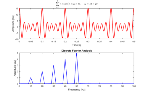
Fast Fourier transform (FFT) is an algorithm that computes the descrete Fourier transform (DFT) of a sequence, or its inverse (IDFT). Fourier analysis converts a signal from its original domain (often time or space) to a representation in the frequency domain and vice versa..

Front panel inputs/outputs are: CH1, CH2, CH3, and CH4 each with a BNC connector (1 MΩ; 200 pF; ±30 V); and OUTPUT BNC connector (50Ω; ±10 V; signal general output capable of a variety of pre-defined, as well as user-defined, signals.)
Rear panel inputs/outputs are: SYSTEM INTERCONNECT DB9 connector (Male connector used for both External triggering, and External sampling inputs. All pins TTL-level except Signal ground: Pin 1 triggering signal input; pin 2 trigger sense output; pin 3 external clock input; pins 6 thru 8 signal ground; pin 9 is the external sampling input); and SERIAL PORT BNC connector (Female connector used linking to the host computer via a Tektronix supplied serial interface cable).
Key Specifications
| Frequency Ranges | DC to 200 kHz |
|---|---|
| Max Real-time Bandwidth | 10 kHz |
| Dynamic Range | 75 dB |
| Standard Channels | 2 |
| Max Channels | 4 |
| Channel Match | ±0.2 dB |
| Transient Capture Samples | 500 K |
| Spectral Lines | 25 to 1600 |
| Input Impedance | 1 MΩ; 200 pF |
| Max Input Level | ±30 V |
| Included Accessories | User Guide; Instrument Program Software; System Simulator Box; Power Cord; and Serial Interface Cable (please specify) |
| Weight | Standard accessories: 11.8 kg (26 lbs) |
| Power | 90 − 250 VAC, 48 to 66 Hz, >120 W |
| Operating Atmospherics | Temperatures: 0 °C to +50 °C; Humidity: 95% for five days; Altitude: Up to 4.8 km (15,000 ft) |
Options
- Opt. 1H: Four Input Channels
- Opt. 2H: 2-CH Zoom
- Opt. 3H: 4-CH Zoom
- Opt. 4H: Signal Generator

