067-0589-00: Difference between revisions
Jump to navigation
Jump to search
No edit summary |
No edit summary |
||
| (8 intermediate revisions by 2 users not shown) | |||
| Line 1: | Line 1: | ||
Rigid Plug-In Extension | {{Plugin Sidebar | ||
|manufacturer=Tektronix | |||
|type=067-0589-00 | |||
|summary=Rigid Plug-In Extension | |||
|image=extender_2.jpg | |||
|caption=067-0589-00 Plug-In Extension | |||
|series=7000-series scopes | |||
|introduced=(?) | |||
|discontinued=(?) | |||
|manuals= | |||
* [[Media:062-1122-00.pdf|067-0589-00 Manual]] | |||
}} | |||
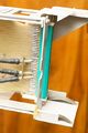
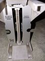
The '''Tektronix 067-0589-00 Rigid Plug-In Extension''' is used for operating [[7000-series plug-ins]] outside the mainframe for repair, maintenance and calibration. | |||
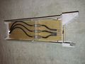
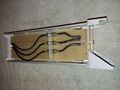
It is based on a printed circuit board and has a guide rail holding a single-width plug-in. | |||
The high-speed signals (vertical, trigger) are carried by coax cables that have BNC couplers in the middle, allowing the signal path to be interrupted for measurement, or to feed an external signal into the mainframe. | |||
==Pictures== | |||
<gallery> | <gallery> | ||
extender_2.jpg | full view of 067-0589-00 | |||
extender_5.jpg | extender inserted into mainframe | |||
extender_4.jpg | 7A26 plugged into extender for servicing | |||
extender_1.jpg | |||
Tek 067-0589-00 1.jpg | Tek 067-0589-00 1.jpg | ||
Tek 067-0589-00 2.jpg | Tek 067-0589-00 2.jpg | ||
| Line 7: | Line 28: | ||
Tek 067-0589-00 4.jpg | Tek 067-0589-00 4.jpg | ||
Tek 067-0589-00 5.jpg | Tek 067-0589-00 5.jpg | ||
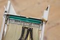
extender_3.jpg | Broken original connector | |||
Tek 067-0589-00 connector replacement 1.jpg | Broken connector replaced by modern alternative | |||
Tek 067-0589-00 connector replacement 2.jpg | | |||
Tek 067-0589-00 connector replacement 3.jpg | | |||
</gallery> | </gallery> | ||
[[Category:7000 series plugins | [[Category:7000 series test and calibration plugins]] | ||
Revision as of 12:22, 9 January 2023

The Tektronix 067-0589-00 Rigid Plug-In Extension is used for operating 7000-series plug-ins outside the mainframe for repair, maintenance and calibration.
It is based on a printed circuit board and has a guide rail holding a single-width plug-in.
The high-speed signals (vertical, trigger) are carried by coax cables that have BNC couplers in the middle, allowing the signal path to be interrupted for measurement, or to feed an external signal into the mainframe.
Pictures
-

full view of 067-0589-00
-
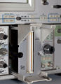
extender inserted into mainframe
-
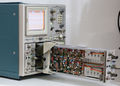
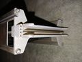
7A26 plugged into extender for servicing
-
-
-
-
-

-
-

Broken original connector
-
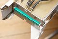
Broken connector replaced by modern alternative
-
-