1121: Difference between revisions
Jump to navigation
Jump to search
No edit summary |
(cat) |
||
| Line 1: | Line 1: | ||
The Tektronix 1121 is a | [[Image:Tek 1121 front.jpg|thumb|350px|right|Tektronix 1121 Amplifier]] | ||
be considered a replacement for the [[121]]. | The '''Tektronix 1121''' is a 5 Hz to 17 MHz amplifier with gain of 100 [[introduced in 1960]]. | ||
is | It can be considered a replacement for the [[121]]. | ||
Maximum output is 2 V<sub>p-p</sub> into a 93 Ω load. The 1121 is AC coupled at the input, but DC coupled at | |||
the output. The output stage is a [[12BY7A]] pentode, V483, biased with 33mA plate current, | the output. The output stage is a [[12BY7A]] pentode, V483, biased with 33mA plate current, | ||
which gives a transconductance of about | which gives a transconductance of about 13 mS. Assuming the tube operates unilaterally, | ||
this gives an impedance of about | this gives an impedance of about 77 Ω at the cathode of V483. Series output resistor | ||
R486, | R486, 30 Ω, makes the output resistance of the 1121 about 107 Ω. (Why is this not | ||
93 Ω?) | |||
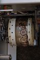
The 1121 uses a [[turret attenuators|turret attenuator]] at the input. | The 1121 uses a [[turret attenuators|turret attenuator]] at the input. | ||
==Specifications== | |||
[[Category:Specifications needed]]''please add'' | |||
==Manuals== | |||
* [http://bama.edebris.com/download/tek/1121/Tek%201121.pdf Tektronix 1121 Manual (PDF)] | * [http://bama.edebris.com/download/tek/1121/Tek%201121.pdf Tektronix 1121 Manual (PDF)] | ||
* [http://w140.com/tek_fcp/tek_1121_tent_fac_cal.pdf Tektronix 1121 Tentative Factory Calibration Procedure (PDF)] | * [http://w140.com/tek_fcp/tek_1121_tent_fac_cal.pdf Tektronix 1121 Tentative Factory Calibration Procedure (PDF)] | ||
==Pictures== | |||
<gallery> | <gallery> | ||
File:Tek 1121 front.jpg | |||
File:Tek 1121 schematic.png | |||
File:Tek 1121 left internal.jpg | |||
File:Tek 1121 right.jpg | |||
File:Tek 1121 top.jpg|Top view | |||
File:Tek 1121 bottom.jpg|Bottom view | |||
File:Tek 1121 turret attenuator.jpg|Turret attenuator | |||
File:Tek 1121 right external.jpg | |||
File:Tek 1121 rear.jpg | |||
</gallery> | </gallery> | ||
[[Category:Amplifiers]] | |||
[[Category:Introduced in 1960]] | |||
Revision as of 02:02, 21 August 2014

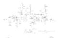
The Tektronix 1121 is a 5 Hz to 17 MHz amplifier with gain of 100 introduced in 1960. It can be considered a replacement for the 121.
Maximum output is 2 Vp-p into a 93 Ω load. The 1121 is AC coupled at the input, but DC coupled at the output. The output stage is a 12BY7A pentode, V483, biased with 33mA plate current, which gives a transconductance of about 13 mS. Assuming the tube operates unilaterally, this gives an impedance of about 77 Ω at the cathode of V483. Series output resistor R486, 30 Ω, makes the output resistance of the 1121 about 107 Ω. (Why is this not 93 Ω?)
The 1121 uses a turret attenuator at the input.
Specifications
please add
Manuals
Pictures
-

-
-
-
-

Top view
-
Bottom view
-
Turret attenuator
-
-


