1121: Difference between revisions
(cat) |
mNo edit summary |
||
| Line 4: | Line 4: | ||
Maximum output is 2 V<sub>p-p</sub> into a 93 Ω load. The 1121 is AC coupled at the input, but DC coupled at | Maximum output is 2 V<sub>p-p</sub> into a 93 Ω load. The 1121 is AC coupled at the input, but DC coupled at | ||
the output. The output stage is a [[12BY7A]] pentode, V483, biased with | the output. The output stage is a [[12BY7A]] pentode, V483, biased with 33 mA plate current, | ||
which gives a transconductance of about 13 mS. Assuming the tube operates unilaterally, | which gives a transconductance of about 13 mS. Assuming the tube operates unilaterally, | ||
this gives an impedance of about 77 Ω at the cathode of V483. Series output resistor | this gives an impedance of about 77 Ω at the cathode of V483. Series output resistor | ||
R486, 30 Ω, makes the output resistance of the 1121 about 107 Ω. (Why is this not | R486, 30 Ω, makes the output resistance of the 1121 about 107 Ω. ''(Why is this not 93 Ω?)'' | ||
93 Ω?) | |||
The 1121 uses a [[turret attenuators|turret attenuator]] at the input. | The 1121 uses a [[turret attenuators|turret attenuator]] at the input. | ||
The front panel probe power connector provides 6.3 V<sub>DC</sub> @ 0.2 A for the heater and +120 V @ 10 mA (regulated) for Type [[P500CF]] cathode-follower probes. | |||
==Specifications== | ==Specifications== | ||
| Line 22: | Line 23: | ||
<gallery> | <gallery> | ||
Tek 1121 front.jpg | |||
Tek 1121 schematic.png | |||
Tek 1121 left internal.jpg | |||
Tek 1121 right.jpg | |||
Tek 1121 top.jpg|Top view | |||
Tek 1121 bottom.jpg|Bottom view | |||
Tek 1121 turret attenuator.jpg|Turret attenuator | |||
Tek 1121 right external.jpg | |||
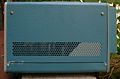
Tek 1121 rear.jpg | |||
</gallery> | </gallery> | ||
[[Category:Amplifiers]] | [[Category:Amplifiers]] | ||
[[Category:Introduced in 1960]] | [[Category:Introduced in 1960]] | ||
Revision as of 03:48, 16 October 2019

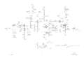
The Tektronix 1121 is a 5 Hz to 17 MHz amplifier with gain of 100 introduced in 1960. It can be considered a replacement for the 121.
Maximum output is 2 Vp-p into a 93 Ω load. The 1121 is AC coupled at the input, but DC coupled at the output. The output stage is a 12BY7A pentode, V483, biased with 33 mA plate current, which gives a transconductance of about 13 mS. Assuming the tube operates unilaterally, this gives an impedance of about 77 Ω at the cathode of V483. Series output resistor R486, 30 Ω, makes the output resistance of the 1121 about 107 Ω. (Why is this not 93 Ω?)
The 1121 uses a turret attenuator at the input.
The front panel probe power connector provides 6.3 VDC @ 0.2 A for the heater and +120 V @ 10 mA (regulated) for Type P500CF cathode-follower probes.
Specifications
please add
Manuals
Pictures
-

-
-
-
-

Top view
-
Bottom view
-
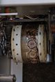
Turret attenuator
-
-


