130: Difference between revisions
No edit summary |
No edit summary |
||
| Line 11: | Line 11: | ||
|designers=Cliff Moulton | |designers=Cliff Moulton | ||
|manuals= | |manuals= | ||
* [[Media:070-231.pdf | Tektronix 130 Manual 070-231]] | * [[Media:070-231.pdf | Tektronix 130 Manual 070-231]] | ||
* [[Media:070-0231-01.pdf | Tektronix 130 Manual 070-231-01]] ( | * [https://vintagetek.org/wp-content/uploads/2020/09/Alan-Hampel-Tektronix-130-Instruction-Manual.pdf 070-231 Manual Restored by Alan Hampel @ vintagetek.org] (includes redrawn schematics) | ||
* [ | * [[Media:070-0231-01.pdf | Tektronix 130 Manual 070-231-01]] (covers both cabinet types) | ||
* [[Media:Tek 130 calibration outline.pdf|Tektronix 130 Calibration Outline ( | * [[Media:tek_type_130_factory_cal_proc.pdf|Tektronix 130 Factory Calibration Procedure]] | ||
* [[Media:Tek 130 calibration outline.pdf|Tektronix 130 Calibration Outline]] (OCR) | |||
}} | }} | ||
The '''Tektronix Type 130''' is a self-contained instrument, designed by [[Cliff Moulton]] and [[introduced in 1959]], that measures inductance and capacitance. | The '''Tektronix Type 130''' is a self-contained instrument, designed by [[Cliff Moulton]] and [[introduced in 1959]], that measures inductance and capacitance. | ||
| Line 33: | Line 34: | ||
==Links== | ==Links== | ||
* Q+A: Type 130 L-C Meter and S-30 Delta Standards. [[Media:Service Scope 18 Feb 1963.pdf | Service Scope No. 18, Feb 1963]]. | * Q+A: Type 130 L-C Meter and S-30 Delta Standards. [[Media:Service Scope 18 Feb 1963.pdf | Service Scope No. 18, Feb 1963]]. | ||
* Silicon Chip, June 2020 | * Silicon Chip, June 2020 – Vintage Workbench – Tektronix T-130 LC Meter: [https://vintagetek.org/wp-content/uploads/2020/09/Silicon-Chip-June-2020-Vintage-Workbench-Tektronix-T-130-LC-Meter-part-one.pdf Part 1] / [https://vintagetek.org/wp-content/uploads/2020/09/Silicon-Chip-July-2020-Vintage-Workbench-Tektronix-T-130-LC-Meter-part-two.pdf Part 2] / [https://vintagetek.org/wp-content/uploads/2020/09/Silicon-Chip-August-2020-Vintage-Workbench-Tektronix-T-130-LC-Meter-part-three.pdf Part 3] (PDFs @ vintagetek.org) | ||
==Internals== | ==Internals== | ||
Revision as of 13:50, 4 November 2022

The Tektronix Type 130 is a self-contained instrument, designed by Cliff Moulton and introduced in 1959, that measures inductance and capacitance.
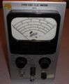
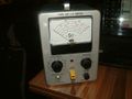
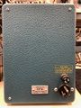
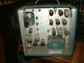
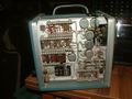
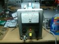
There are at least two versions of Type 130. Early units (SN 101-5000) have a narrow boxy case that slides off the chassis, backlit meter, and are marked "TYPE 130 L,C METER". At some point between SN 101 and SN 842, the case color changed from brown to blue. Later units (SN 5001-Up) have a wider, rounded case with side panels that pop off, blue paint, non-backlit meter, and are marked "TYPE 130 L-C METER".
Key Specifications
| Ranges | 3, 10, 30, 100 or 300 pF / 3, 10, 30, 100 or 300 μH full scale |
|---|---|
| Accuracy | 3% FS, 1% FS with "careful" calibration using S-30 Delta Standard |
| Measurement voltage | <1 V for capacitors, <0.25 V for inductors, 120-140 kHz |
| Guard output | 250 Ω source impedance, can drive 200 pF |
| DUT connection | UHF connector (DUT) + 4 mm jack (guard) |
Links
- Q+A: Type 130 L-C Meter and S-30 Delta Standards. Service Scope No. 18, Feb 1963.
- Silicon Chip, June 2020 – Vintage Workbench – Tektronix T-130 LC Meter: Part 1 / Part 2 / Part 3 (PDFs @ vintagetek.org)
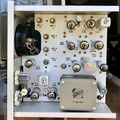
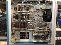
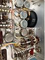
Internals
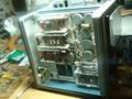
The 130 contains an LC oscillator with a tank circuit formed by the device under test and a capacitor or inductor internal to the 130. The oscillator's frequency is measured by mixing it down using a fixed reference frequency, generating a pulse at each zero-crossing, and integrating (low-pass filtering) the pulse train. This produces a voltage that is proportional to the frequency difference between the LC oscillator and the reference oscillator. This voltage is displayed on a d'Arsonval (moving coil) meter on the front panel of the 130.
Pictures
130 External
-
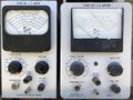
130 Variants
-
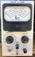
Tek 130 SN < 5001 Front
-
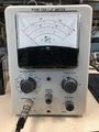
Tek 130 130 SN > 5000 Front
-
Early (Brown Era) Type 130
-
Early (Brown Era) Type 130
-
-
-
-
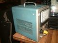
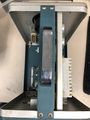
Type 130 Rear
-
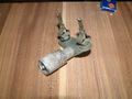
013-0001-00 test adapter


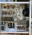
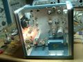
130 Internal
-

Type 130 Internal RHS
-
Tek 130 SN < 5001 RHS
-
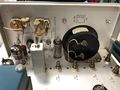
Type 130 Internal LHS
-
Tek 130 SN < 5001 LHS (w line plug mod)
-
Type 130 Top w/o Cover
-
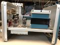
Type 130 Bottom
-
Type 130 Internal #1
-
Type 130 Internal #1
-
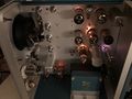
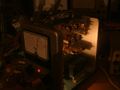
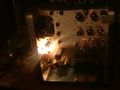
Type 130 Internal Live
-
-
-
-
-
-
-


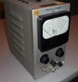
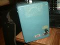
130 SN 842
At serial number 842, the shape is still narrow and boxy, but with a blue case.


