181: Difference between revisions
No edit summary |
No edit summary |
||
| (11 intermediate revisions by 4 users not shown) | |||
| Line 1: | Line 1: | ||
The Tektronix Type 181 is a time mark generator [[introduced in 1955]]. There is a benchtop version, | {{Instrument Sidebar | ||
the 181, and a rackmount version, the RM181. MOD 110 substitutes a oven- | |manufacturer=Tektronix | ||
|model=181 | |||
thereby achieving 2 parts per million | |class=Pulse generator | ||
frequency stability in a 24 hour period, the same stability as the [[180A]]. | |series= | ||
|summary=Time mark generator | |||
|image=181_PC_ISO.jpg | |||
|caption=181, early version | |||
|introduced=1955 | |||
|discontinued=(?) | |||
|designers= | |||
|manuals= | |||
* [[Media:070-292.pdf|Tektronix 181 Manual]] (sn 6917, color schematics, PDF) | |||
* [https://w140.com/mmm/tek-181.pdf Tektronix 181 Manual (PDF)] | |||
}} | |||
The '''Tektronix Type 181''' is a time mark generator [[introduced in 1955]]. There is a benchtop version, the 181, and a rackmount version, the RM181. | |||
MOD 110 substitutes a oven-stabilized1 MHz crystal oscillator (OCXO), the CO181 (Tek part number [[158-007]]), thereby achieving 2 parts per million frequency stability in a 24 hour period, the same stability as the [[180A]]. | |||
A 181 with the OCXO mod is a "181 S1". | A 181 with the OCXO mod is a "181 S1". | ||
==Internals == | |||
Internally, the 181 is similar to the [[180A|180]]. | Internally, the 181 is similar to the [[180A|180]]. | ||
The oscillator drives a chain of synchronized monostable multivibrators. | The oscillator drives a chain of synchronized monostable multivibrators. | ||
Each multivibrator is triggered by the output of the previous stage, and | Each multivibrator is triggered by the output of the previous stage, and cannot be triggered again for the duration of its pulse width. | ||
cannot be triggered again for the duration of its pulse width. In the 181, | In the 181, the pulse width ratio of one stage to the next is 1:10, i.e. when a stage triggers on a pulse at its input, it propagates that event to its output, but inhibits the next nine pulses (by time, not by counting). | ||
that event to its output, but inhibits the next nine pulses | |||
not by counting | |||
The 181 also provides a | The 181 also provides a 10 MHz output. This is generated by a 10 MHz resonator that is driven by an amplified and waveshaped copy of the 1 MHz crystal oscillator output. | ||
is driven by an amplified and waveshaped copy of the | Since it is a harmonic, the 10 MHz output has same relative frequency accuracy as the reference oscillator. | ||
Since it is a harmonic, the | |||
the reference oscillator. | |||
The power supply of the 181 produces + | The power supply of the 181 produces +300 V and −150 V regulated voltages and +400 V, −8 V, and −25 V unregulated. | ||
+ | The voltage reference is a [[5651]] tube. The output tubes for both regulators are [[12B4]] and the feedback amplifier tubes are [[6AU6]]. | ||
The output tubes for both regulators are [[12B4]] and the feedback amplifier | The 181 does not contain a fan or a [[thermal cutoff]]. | ||
tubes are [[6AU6]]. The 181 does not contain a fan or a [[thermal cutoff]]. | |||
==Pictures == | |||
<gallery> | <gallery> | ||
Tek 181.jpg|181 | |||
Tek rm181.jpg|RM181 | |||
181_PC_ISO.jpg|181, early version | |||
181_PC_Front.jpg|181, early version, front | |||
181_PC_Left.jpg|181, early version, left side | |||
181_PC_Right.jpg|181, early version, right side | |||
Tek co181.jpg|CO181 oven-stabilized oscillator | |||
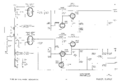
Tek 181 block.png|Block diagram | |||
Tek 181 oscillator and multiplier.png|oscillator and multiplier | |||
Tek 181 frequency dividers.png|frequency dividers | |||
Tek 181-switching detail.png|switching detail | |||
Tek 181 power supply.png|power supply | |||
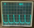
Tek rm181 1us output2.jpg|Output waveform of RM181 set for 1 us period | |||
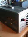
Tek 181 later style rounded case.jpg|Later style case, rounded corners | |||
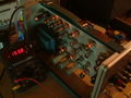
Tek 181 left internal on.jpg|Left internal view, powered up | |||
Tek 181 late internal.jpg|Internal view, late version | |||
</gallery> | </gallery> | ||
[[Category:Time mark generators]] | |||
[[Category:Introduced in 1955]] | |||
Revision as of 07:05, 18 August 2021

The Tektronix Type 181 is a time mark generator introduced in 1955. There is a benchtop version, the 181, and a rackmount version, the RM181.
MOD 110 substitutes a oven-stabilized1 MHz crystal oscillator (OCXO), the CO181 (Tek part number 158-007), thereby achieving 2 parts per million frequency stability in a 24 hour period, the same stability as the 180A. A 181 with the OCXO mod is a "181 S1".
Internals
Internally, the 181 is similar to the 180. The oscillator drives a chain of synchronized monostable multivibrators. Each multivibrator is triggered by the output of the previous stage, and cannot be triggered again for the duration of its pulse width. In the 181, the pulse width ratio of one stage to the next is 1:10, i.e. when a stage triggers on a pulse at its input, it propagates that event to its output, but inhibits the next nine pulses (by time, not by counting).
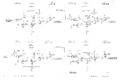
The 181 also provides a 10 MHz output. This is generated by a 10 MHz resonator that is driven by an amplified and waveshaped copy of the 1 MHz crystal oscillator output. Since it is a harmonic, the 10 MHz output has same relative frequency accuracy as the reference oscillator.
The power supply of the 181 produces +300 V and −150 V regulated voltages and +400 V, −8 V, and −25 V unregulated. The voltage reference is a 5651 tube. The output tubes for both regulators are 12B4 and the feedback amplifier tubes are 6AU6. The 181 does not contain a fan or a thermal cutoff.
Pictures
-
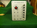
181
-
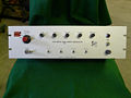
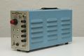
RM181
-
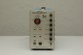
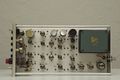
181, early version
-
181, early version, front
-

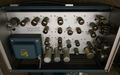
181, early version, left side
-
181, early version, right side
-
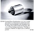
CO181 oven-stabilized oscillator
-
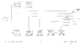
Block diagram
-

oscillator and multiplier
-
frequency dividers
-

switching detail
-
power supply
-
Output waveform of RM181 set for 1 us period
-
Later style case, rounded corners
-
Left internal view, powered up
-
Internal view, late version


