213: Difference between revisions
No edit summary |
No edit summary |
||
| Line 1: | Line 1: | ||
{{Oscilloscope Sidebar| | {{Oscilloscope Sidebar | | ||
title=Tektronix 213| | title=Tektronix 213 | | ||
image= | image=Tek213-front-1.jpg | | ||
caption=Tektronix 213, front view| | caption=Tektronix 213, front view | | ||
introduced=1975 | | introduced=1975 | | ||
discontinued=1988 | | discontinued=1988 | | ||
summary=Miniature portable 1 MHz oscilloscope and TRMS digital multimeter| | summary=Miniature portable 1 MHz oscilloscope and TRMS digital multimeter | | ||
manuals= | manuals= | ||
}} | }} | ||
| Line 50: | Line 50: | ||
<gallery> | <gallery> | ||
Tek213-front-1.jpg | Tek 213 front | |||
Tektronix 213DMM pic 2.jpg|In DMM mode | |||
213-Stefan-140333.jpg | 213 with pouch | |||
213-Stefan-140342.jpg | right side | |||
213-Stefan-162337.jpg | without covers, bottom/left | |||
213-Stefan-162344.jpg | without covers, left | |||
213-Stefan-162352.jpg | without covers, top | |||
213-Stefan-172313.jpg | without covers, operating, top/right | |||
213-Stefan-162409.jpg | Plastic case halves | |||
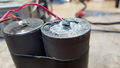
213-Stefan-162419.jpg | Original battery, corroded | |||
213-Stefan-162428.jpg | |||
213-Stefan-162443.jpg | |||
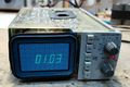
213-Stefan-172154.jpg | In DMM mode | |||
213-Stefan-172309.jpg | |||
213-Stefan-172243.jpg | In scope mode | |||
213-Stefan-172258.jpg | |||
Tektronix 213DMM pic 1.jpg | Catalog image, front | |||
Tektronix 213DMM side view.jpg | Catalog image, side | |||
</gallery> | |||
===Schematics=== | |||
<gallery> | |||
Tektronix 213DMM Attenuator and Input Amplifier.jpg|Attenuator and Input Amplifier Schematic | |||
Tektronix 213DMM GM and RMS Converter.jpg|GM and RMS Converter Schematic | |||
Tektronix 213DMM Battery Charger and Power Supply.jpg|Battery Charger and Power Supply Schematic | |||
Tektronix 213DMM HV and CRT.jpg|HV and CRT Schematic | |||
Tektronix 213DMM A-D Converter and Character Generator.jpg|A-D Converter and Character Generator Schematic | |||
</gallery> | </gallery> | ||
Revision as of 10:18, 15 January 2017

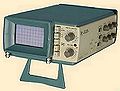
The Tektronix 213 is a miniature portable oscilloscope introduced in 1975. It combines a 3½-digit DMM and a 1 MHz single channel scope in one unit. The maximum sweep rate is 0.4 μs/div with ×10 sweep magnifier.
The 213 provides true RMS voltage and current measurements. It is battery or AC line powered.
Key Specifications
| — Multimeter Section — | |
| DC Volts | 0.1 V to 1000 V, Input Resistance: 10 MΩ Accuracy, 0.1 V & 1 V: ±0.1%, ±3 counts; 10 V & 100 V: ±0.15%, ±1 count; 1000 V: ±0.2%, ±1 count |
| True RMS Volts | DC Volts |
| DC Current | 0.1 to 1000 mA Accuracy: 0.1 mA: ±0.5%, ±3 counts; 1 mA – 1000 mA: ±0.25%, ±3 counts |
| True RMS Current | 0.1 to 1000 mA Accuracy, 0.1 mA: ±2.5%, ±5 counts (DC); ±1.5%, ±5 counts (40 Hz – 4 KHz); ±4.5%, ±5 counts (4 KHz - 40 KHz); 1 mA – 1000 mA: ±2.5%, ±5 counts (DC); ±1.5%, ±5 counts (40 Hz – 4 KHz); ±3.5%,±5 counts (4 KHz - 40 KHz) |
| Current range input resistance | 0.1 mA: 1000 Ω; 1 mA: 100 Ω; 10 mA: 10.2 Ω; 100 mA: 1.2 Ω; 1000 mA: 0.3 Ω |
| Resistance | 1 KΩ: ±0.5%, ±3 counts; 10 KΩ – 1 MΩ: ±0.5%, ±1 count; 10 MΩ: ±1%, ±1 count |
| — Oscilloscope Section — | |
| Voltage ranges | 5 mV/Div to – 100 V/Div, ±3% |
| Bandwidth (Voltage) | DC – 1 MHz (at 10 mV/Div and below, 400 kHz) |
| Current ranges | 5 µA/Div to 100 mA/Div, ±3% |
| Bandwidth (Current) | DC – 200 kHz (5 µA/Div – 10 µA/Div); DC – 400 kHz (20 µA/Div – 200 mA/Div) |
| Input resistance | 10 MΩ // 150 pF (5 mV/Div – 1 V/Div), 100 pF (2 V/Div to – 100 V/Div) |
| Rise time | 875 ns (5mV – 10mV/DIV); 350 ns (20 mV – 100 V/Div) |
| Sweep | 500 ms/Div – 2 µs/Div, ±5% (magnified or unmagnified) |
| Batteries | 2 × “D” NiCd cells |
| Operating time | 3.5 hours typical at maximum intensity after full charge cycle |
| Charge time | 16 h |
| Mains power | 90 – 136 VAC. 48 – 62 Hz (Option 1: 180 – 250 VDC. or 180 – 250 VAC, 48 – 62 Hz) |
| Power consumption | Less than 8 watts |
Links
- EEVblog #628 – Tektronix 213 Vintage Portable Oscilloscope Teardown Video and Photo Set
- Tektronix 213 DMM Repair Progress video
Internals
The 213 makes use of two Tek-made custom chips, the 155-0048-01 trigger sweep circuit, and the 155-0114-00 7-segment character generator in the DVM circuit. In addition, it includes some standard opamps (741, 324) and a 4-digit decimal counter (Mostek MK5007).
Pictures
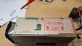
-

Tek 213 front
-
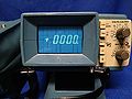
In DMM mode
-
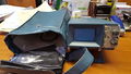
213 with pouch
-
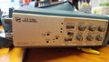
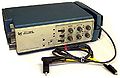
right side
-
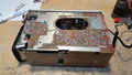
without covers, bottom/left
-
without covers, left
-

without covers, top
-
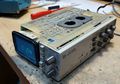
without covers, operating, top/right
-
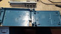
Plastic case halves
-
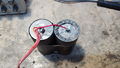
Original battery, corroded
-
-

-
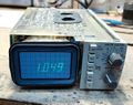
In DMM mode
-
-
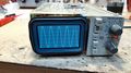
In scope mode
-

-
Catalog image, front
-
Catalog image, side


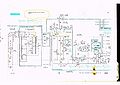
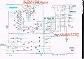
Schematics
-
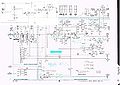
Attenuator and Input Amplifier Schematic
-
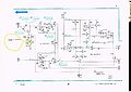
GM and RMS Converter Schematic
-
Battery Charger and Power Supply Schematic
-
HV and CRT Schematic
-

A-D Converter and Character Generator Schematic


