230: Difference between revisions
No edit summary |
No edit summary |
||
| Line 1: | Line 1: | ||
{{ | {{Plugin Sidebar 2 | | ||
title=Tektronix 230 | | title=Tektronix 230 | | ||
summary=Digital Unit | | summary=Digital Unit | | ||
| Line 6: | Line 6: | ||
introduced=1967 | | introduced=1967 | | ||
discontinued=(?) | | discontinued=(?) | | ||
series=[[568|568 sampling scope]] | | |||
manuals= | manuals= | ||
* [http://bama.edebris.com/download/tek/230/tek%20230.v6.pdf Tektronix 230 Manual (PDF)] | * [http://bama.edebris.com/download/tek/230/tek%20230.v6.pdf Tektronix 230 Manual (PDF)] | ||
* [http://exodus.poly.edu/~kurt/tek_230_late.pdf Tektronix 230 Manual (late version, PDF)] | * [http://exodus.poly.edu/~kurt/tek_230_late.pdf Tektronix 230 Manual (late version, PDF)] | ||
* [http://w140.com/tek_readout_oscilloscopes_1968_catalog.pdf "Digital Readout Introduction" in 1968 Catalog (PDF)] | |||
* [http://w140.com/tek_readout_oscilloscopes_1968_catalog.pdf "Digital Readout Introduction" in 1968 Catalog (PDF)] | * [http://w140.com/tek_readout_oscilloscopes_1968_catalog.pdf "Digital Readout Introduction" in 1968 Catalog (PDF)] | ||
}} | }} | ||
| Line 22: | Line 22: | ||
[[tunnel diodes]]. It makes some use of integrated circuits and extensive use of | [[tunnel diodes]]. It makes some use of integrated circuits and extensive use of | ||
[http://en.wikipedia.org/wiki/Reed_relay reed relays]. | [http://en.wikipedia.org/wiki/Reed_relay reed relays]. | ||
The 230 was distributed by itself (usually for use with a 568) and also | |||
as a component of larger integrated test and measurement systems | |||
such as the [[S-3100]]. | |||
The 230 is programmable, which means that its circuitry can be controlled remotely, | The 230 is programmable, which means that its circuitry can be controlled remotely, | ||
| Line 32: | Line 36: | ||
limit, within the limits, or above the upper limit. | limit, within the limits, or above the upper limit. | ||
The minimal system configuration with a 230 is just the 230 connected to the 568. Five out of six | The minimal system configuration with a 230 is just the 230 connected to the 568. Five out of six | ||
of the connectors on the rear panel of the 230 can be ignored for basic use. J101 on the rear of the | of the connectors on the rear panel of the 230 can be ignored for basic use. J101 on the rear of the | ||
| Line 44: | Line 43: | ||
this is the CRT intensifier signal, which is sent by the 230 to the 568. This signal intensifies | this is the CRT intensifier signal, which is sent by the 230 to the 568. This signal intensifies | ||
the trace in the various zones, which are configured on the 230 or remotely using a [[241]] programmer. | the trace in the various zones, which are configured on the 230 or remotely using a [[241]] programmer. | ||
==Internals== | |||
The power supply in the Tektronix 230 is linear and provides regulated of +50 V, +12 V, +3.8 V, +1.75 V, | |||
-3.5 V, and -50 V. It also provides a +255 V unregulated output. The power supply transformer, electrolytic | |||
capacitors, and output transistors are part of the chassis, not a removable unit. Thue regulator circuits | |||
are on a circuit card. | |||
Most of the circuitry of the 230 is on circuit cards that plug into a backplane bus. | Most of the circuitry of the 230 is on circuit cards that plug into a backplane bus. | ||
==Pictures== | |||
<gallery> | <gallery> | ||
File:230 front.jpg | 230's Front | |||
File:230 insides.jpg | 230's insides | |||
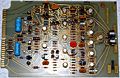
File:230 zone generator card.jpg | Zone generator PCB | |||
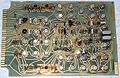
File:230 comparator card.jpg | comparator PCB | |||
File:230 memory card.jpg | memory PCB | |||
File:230 clock board.jpg | clock PCB | |||
File:230 backplane.jpg | backplane | |||
File:230 power supply.jpg | power supply | |||
File:230 rear.jpg | 230's rear | |||
File:230_568_0.JPG | 230 and 568 measuring rise time | |||
</gallery> | </gallery> | ||
[[Category: | [[Category:Accessories]] | ||
Revision as of 23:44, 15 July 2015
Template:Plugin Sidebar 2 The Tektronix 230 is a digital readout introduced in 1967 for the 568 sampling oscilloscope.
The 568 and 230 replaced the 567 and its digital unit plug-ins, the 6R1 and 6R1A. Unlike the 6R1 and 6R1A, the 230 is freestanding unit, not a plug-in. Just like the 6R1A was an evolutionary step forward from the 6R1, the circuitry in the 230 is an evolutionary step forward from the 6R1A. The 230 does not contain any tubes or tunnel diodes. It makes some use of integrated circuits and extensive use of reed relays.
The 230 was distributed by itself (usually for use with a 568) and also as a component of larger integrated test and measurement systems such as the S-3100.
The 230 is programmable, which means that its circuitry can be controlled remotely, using multipin connectors located on the rear panel. The rear panel contains six connectors, four for remote control, one for connection to the 568 oscilloscope, and one that provides a binary-coded decimal representation of the number that is displayed on the digital readout on the 230. Like the 6R1 and 6R1A, the 230 allows upper and lower limits to be set on voltage or time, and it has front-panel lamps and rear panel signals that show whether the current measurement is below the lower limit, within the limits, or above the upper limit.
The minimal system configuration with a 230 is just the 230 connected to the 568. Five out of six of the connectors on the rear panel of the 230 can be ignored for basic use. J101 on the rear of the 230 connects to the J101 on the rear of the 568. This connection is required since it brings the sampled signal from the 568 to the 230. The 230 does not control the 568. The 568 sends signals and the 230 displays them on the Nixie readout and generates control signals on its rear panel connectors. One exception to this is the CRT intensifier signal, which is sent by the 230 to the 568. This signal intensifies the trace in the various zones, which are configured on the 230 or remotely using a 241 programmer.
Internals
The power supply in the Tektronix 230 is linear and provides regulated of +50 V, +12 V, +3.8 V, +1.75 V, -3.5 V, and -50 V. It also provides a +255 V unregulated output. The power supply transformer, electrolytic capacitors, and output transistors are part of the chassis, not a removable unit. Thue regulator circuits are on a circuit card.
Most of the circuitry of the 230 is on circuit cards that plug into a backplane bus.
Pictures
-
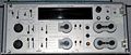
230's Front
-
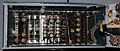
230's insides
-
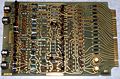
Zone generator PCB
-
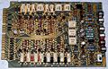
comparator PCB
-
memory PCB
-
clock PCB
-
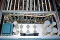
backplane
-
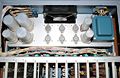
power supply
-
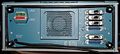
230's rear
-
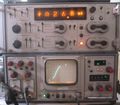
230 and 568 measuring rise time


