2755: Difference between revisions
No edit summary |
No edit summary |
||
| (5 intermediate revisions by the same user not shown) | |||
| Line 1: | Line 1: | ||
{{ | {{Instrument Sidebar | ||
|class=Spectrum Analyzer | |||
summary=Spectrum Analyzer | |manufacturer=Tektronix | ||
image= Tek_2755P_Waveform_image.jpg | | |model=2755AP | ||
caption=Tektronix 2755AP | | |summary=21 GHz Spectrum Analyzer | ||
introduced=1987 | | |image= Tek_2755P_Waveform_image.jpg | ||
discontinued=1993 | | |caption=Tektronix 2755AP | ||
manuals= | |introduced=1987 | ||
|discontinued=1993 | |||
* [[Media: Tek_2755_Catalog_Spec_1987.pdf| Tektronix 2755 Introduction Spec (PDF, OCR)]] | |manuals= | ||
* [[Media: Tek_2755_Catalog_Spec_1991.pdf| Tektronix 2755 Final Spec (PDF, OCR)]] | * Operator, Service, and Programmer Manuals needed [[Category:Manual needed]] | ||
* [[Media:Tek_2755_Catalog_Spec_1987.pdf| Tektronix 2755 Introduction Spec (PDF, OCR)]] | |||
* [[Media:Tek_2755_Catalog_Spec_1991.pdf| Tektronix 2755 Final Spec (PDF, OCR)]] | |||
}} | }} | ||
The '''Tektronix 2755AP''' is a spectrum analyzer with a frequency range of 10 kHz to 21 GHz in coax, and up to 325 GHz with external waveguide mixers. The '''P''' suffix designation indicates GPIB '''P'''rogrammability. The minimum resolution bandwidth is 100 Hz, and provides measurement resolution proportional to the frequency accuracy or span. In addition to conventional digital storage features, non-volatile memory (NVRAM) stores up to 9 separate waveforms with their readouts and markers, for later recall for additional analysis and comparison, and 10 control settings. Also, store up to 39 preselector peaks and 12 external band peaks. The instrument can selectively count one particular signal out of several that may be present at its input. | The '''Tektronix 2755AP''' is a spectrum analyzer with a frequency range of 10 kHz to 21 GHz in coax, and up to 325 GHz with external waveguide mixers. The '''P''' suffix designation indicates GPIB '''P'''rogrammability. The minimum resolution bandwidth is 100 Hz, and provides measurement resolution proportional to the frequency accuracy or span. In addition to conventional digital storage features, non-volatile memory (NVRAM) stores up to 9 separate waveforms with their readouts and markers, for later recall for additional analysis and comparison, and 10 control settings. Also, store up to 39 preselector peaks and 12 external band peaks. The instrument can selectively count one particular signal out of several that may be present at its input. | ||
| Line 23: | Line 24: | ||
{{BeginSpecs}} | {{BeginSpecs}} | ||
{{Spec | Frequency | {{Spec | Frequency | 10 kHz to 21 GHz, up to 325 GHz with external waveguide mixers }} | ||
{{Spec | Frequency Span | 100 Hz/div to 10 GHz/div in 1-2-5 sequence (plus 0 Hz and MAX) }} | |||
{{Spec | Resolution Bandwidth | 6 dB bandwidths from 100 Hz to 3 MHz in decade steps }} | |||
{{Spec | Frequency Span | |||
{{Spec | Resolution Bandwidth | |||
{{Spec | RF Input impedance | 50 Ω }} | {{Spec | RF Input impedance | 50 Ω }} | ||
{{Spec | Maximum Safe Input Power | | {{Spec | Maximum Safe Input Power | 1 W (+30 dBm) CW, 75 W peak (1 µs pulse, 0.1% duty factor) }} | ||
{{Spec | RF Attenuator | 0 dB to 60 dB, 10 dB steps }} | |||
{{Spec | Reference Level | -117 dBm to +40 dBm (+30 dBm maximum safe input) }} | |||
{{Spec | RF Attenuator | |||
{{Spec | Reference Level | |||
{{Spec | LO Output Power (2 to 6 GHz) | 1st LO: +7.5 dBm to +15 dBm; 2nd LO: -22 dBm to +15 dBm; Must be terminated into 50 Ω when they are not connector to an external device }} | {{Spec | LO Output Power (2 to 6 GHz) | 1st LO: +7.5 dBm to +15 dBm; 2nd LO: -22 dBm to +15 dBm; Must be terminated into 50 Ω when they are not connector to an external device }} | ||
{{Spec | Sweep Speed | {{Spec | Sweep Speed | 5 s to 2 µs in 1, 2, 5 sequence (10 s/div in auto) }} | ||
{{Spec | Video Bandwidth | {{Spec | Video Bandwidth | 0.3 Hz to 30 kHz }} | ||
{{Spec | Displayed Average Noise | −125 dBm }} | {{Spec | Displayed Average Noise | −125 dBm }} | ||
{{Spec | | {{Spec | Dynamic Range | Display 90 dB, Compression to noise 134 dBm }} | ||
{{Spec | Calibrator (Cal out) | 50 Ω, -20 dBm ±0.3 dB at 100 MHz }} | |||
{{Spec | Calibrator (Cal out) | | {{Spec | Power | 90 − 132 V<sub>AC</sub>, 48 to 448 Hz; 180 – 250 V<sub>AC</sub>, 48 to 72 Hz. At 115 V<sub>AC</sub>, 60 Hz, 210 W max with all options }} | ||
{{Spec | | |||
{{Spec | Weight | 27 kg (60 lbs) }} | {{Spec | Weight | 27 kg (60 lbs) }} | ||
{{EndSpecs}} | {{EndSpecs}} | ||
</small> | |||
'''Options''' | |||
* Opt. 01: Add preselector for the 1.7 to 21 GHz band and limiter for 1st mixer below 1.8 GHz | * Opt. 01: Add preselector for the 1.7 to 21 GHz band and limiter for 1st mixer below 1.8 GHz | ||
* Opt. 07: | * Opt. 07: 75 Ω dBmV input and calibration in addition to 50Ω dBm input and calibration; Includes BNC male to female adapter connector, 42 inch BNC to BNC connector 75Ω coax cable | ||
* Opt. 21: High Performance 18 to 40 GHz Waveguide Mixer Set includes two mixers (18 to 26.5 GHz, and 26.5 GHz to 40 GHz) | * Opt. 21: High Performance 18 to 40 GHz Waveguide Mixer Set includes two mixers (18 to 26.5 GHz, and 26.5 GHz to 40 GHz) | ||
* Opt. 22: High Performance 18 to 60 GHz Waveguide Mixer Set includes three mixers (18 to 26.5 GHz, 26.5 GHz to 40 GHz, and 40 GHz to 60 GHz) | * Opt. 22: High Performance 18 to 60 GHz Waveguide Mixer Set includes three mixers (18 to 26.5 GHz, 26.5 GHz to 40 GHz, and 40 GHz to 60 GHz) | ||
| Line 66: | Line 57: | ||
* Opt. 42: Replaces MARKER/VIDEO input port on the rear panel with a 110 MHz IF output port that provides a 3 dB signal bandwidth ≥4.5 MHz | * Opt. 42: Replaces MARKER/VIDEO input port on the rear panel with a 110 MHz IF output port that provides a 3 dB signal bandwidth ≥4.5 MHz | ||
* Opt. 45: MATE/CIIL language | * Opt. 45: MATE/CIIL language | ||
</small> | |||
==Pictures== | ==Pictures== | ||
| Line 72: | Line 63: | ||
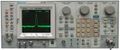
Tek_2755P_Waveform_image.jpg | Tek_2755P_Waveform_image.jpg | ||
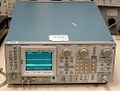
Tek_2755_2.jpg | Tek_2755_2.jpg | ||
Tektronix 2755AP.jpg | courtesy of wellenkino.de | |||
</gallery> | </gallery> | ||
[[Category:Spectrum analyzers]] | [[Category:Spectrum analyzers]] | ||
Latest revision as of 11:57, 18 December 2023

The Tektronix 2755AP is a spectrum analyzer with a frequency range of 10 kHz to 21 GHz in coax, and up to 325 GHz with external waveguide mixers. The P suffix designation indicates GPIB Programmability. The minimum resolution bandwidth is 100 Hz, and provides measurement resolution proportional to the frequency accuracy or span. In addition to conventional digital storage features, non-volatile memory (NVRAM) stores up to 9 separate waveforms with their readouts and markers, for later recall for additional analysis and comparison, and 10 control settings. Also, store up to 39 preselector peaks and 12 external band peaks. The instrument can selectively count one particular signal out of several that may be present at its input.
The single and delta markers provide direct readout of frequency and amplitude information of any point along any displayed trace. Or, get the relative (delta) frequency and amplitude information between any two points along any displayed trace or between traces.
Additional features include: Continuous Resolution Frequency Tuning, Up to 90 dB Viewable Dynamic Range, Built-in Frequency Counters Provide Frequency Determination to within 0.0000001%, Sensitivities to -134 dBm, Built-in Intelligence for Signal Processing/Marker Functions, Push Button Occupied-Bandwidth/Noise Normalization Functions, Macro Capability with Nonvolatile Memory, Optional Switch-Selectable 50/75Ω Impedances, Direct Screen Data Plots without a Controller, and optional MATE/CIIL Compatibility for Military Applications.
Front panel inputs/outputs are: RF INPUT 50Ω N connector (Input connector for RF signals to 21 GHz. If input signal has a dc component use a blocking capacitor in line with the signals); CAL OUT BNC connector (Calibrator output provides -20 dBm 100 MHz signal and a comb of frequency markers 100 MHz apart); 1ST LO OUTPUT SMA connector (Provides access to the output of the 1st local oscillator. Must be terminated into 50 Ω when they are not connector to an external device); 2ND LO OUTPUT SMA connector (Provides access to the output of the 2nd local oscillator. Must be terminated into 50 Ω when they are not connector to an external device); EXTERNAL MIXER RF INPUT TNC connector (50Ω); and Camera Power .
Rear panel inputs/outputs are: PROBE POWER (Provides operating voltages (+5 V, -15 V, +15 V; 100 mA max each) for active probes); HORIZ|TRIG (EXT IN) BNC connector (A dual function connector: When in External Triggering mode the connector is an AC coupled input for trigger signals. When the TIME/DIV selection is EXT the connector is a DC coupled input for horizontal sweep voltages); MARKER|VIDEO (EXT IN) BNC connector (Interfaces to a Tektronix 1405 TV Adapter to display an externally-generated marker); EXT REF IN BNC connector (A 50Ω input for a 1, 2, 5, or 10 MHz external reference signal; HORIZ (OUTPUT) BNC connector (Supplies a 0.5 V/div horizontal signal); VERT (OUTPUT) BNC connector (Provides access to the video signal with 0.5 V for each division of displayed video above or below the center line.); PEN LIFT (OUTPUT) BNC connector (Provides access to a TTL compatible signal to lift the pen of a chart recorder during sweep retrace. In Opt. 42 instruments, use this connector to input external video signals if pin 1 of the ACCESSORIES connector is grounded); 10 MHz IF (OUTPUT) BNC connector (Provides access to the output of the 10 MHz IF); J104 ACCESSORY female DB25 connector (Provides bidirectional access to the instrument bus)); IEEE STD 488 PORT GPIB interface.
Key Specifications
| Frequency | 10 kHz to 21 GHz, up to 325 GHz with external waveguide mixers |
|---|---|
| Frequency Span | 100 Hz/div to 10 GHz/div in 1-2-5 sequence (plus 0 Hz and MAX) |
| Resolution Bandwidth | 6 dB bandwidths from 100 Hz to 3 MHz in decade steps |
| RF Input impedance | 50 Ω |
| Maximum Safe Input Power | 1 W (+30 dBm) CW, 75 W peak (1 µs pulse, 0.1% duty factor) |
| RF Attenuator | 0 dB to 60 dB, 10 dB steps |
| Reference Level | -117 dBm to +40 dBm (+30 dBm maximum safe input) |
| LO Output Power (2 to 6 GHz) | 1st LO: +7.5 dBm to +15 dBm; 2nd LO: -22 dBm to +15 dBm; Must be terminated into 50 Ω when they are not connector to an external device |
| Sweep Speed | 5 s to 2 µs in 1, 2, 5 sequence (10 s/div in auto) |
| Video Bandwidth | 0.3 Hz to 30 kHz |
| Displayed Average Noise | −125 dBm |
| Dynamic Range | Display 90 dB, Compression to noise 134 dBm |
| Calibrator (Cal out) | 50 Ω, -20 dBm ±0.3 dB at 100 MHz |
| Power | 90 − 132 VAC, 48 to 448 Hz; 180 – 250 VAC, 48 to 72 Hz. At 115 VAC, 60 Hz, 210 W max with all options |
| Weight | 27 kg (60 lbs) |
Options
- Opt. 01: Add preselector for the 1.7 to 21 GHz band and limiter for 1st mixer below 1.8 GHz
- Opt. 07: 75 Ω dBmV input and calibration in addition to 50Ω dBm input and calibration; Includes BNC male to female adapter connector, 42 inch BNC to BNC connector 75Ω coax cable
- Opt. 21: High Performance 18 to 40 GHz Waveguide Mixer Set includes two mixers (18 to 26.5 GHz, and 26.5 GHz to 40 GHz)
- Opt. 22: High Performance 18 to 60 GHz Waveguide Mixer Set includes three mixers (18 to 26.5 GHz, 26.5 GHz to 40 GHz, and 40 GHz to 60 GHz)
- Opt. 23: GRASP software, National’s PC2A (GPIB) card, and GPIB cable)
- Opt. 27: Epson LT-386SX, GRASP software, National’s PC2A (GPIB) card, and GPIB cable
- Opt. 28: Deskpro 386S, Model 40, GRASP software, National’s PC2A (GPIB) card, and GPIB cable
- Opt. 29: Epson printer. Includes: Epson FX-86E printer and parallel interface cable
- Opt. 30: Rackmount with handles for 19 in. rack
- Opt. 31: Rackmount with handles for 19 in. rack with rear panel input/output capability (no front panel inputs)
- Opt. 39: Non-lithium batteries for battery-backed memory
- Opt. 41: Digital Microwave Radio Measurement Enhancement Package
- Opt. 42: Replaces MARKER/VIDEO input port on the rear panel with a 110 MHz IF output port that provides a 3 dB signal bandwidth ≥4.5 MHz
- Opt. 45: MATE/CIIL language
Pictures
-
-
-
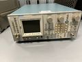
courtesy of wellenkino.de

