284: Difference between revisions
No edit summary |
(Added oscilloscope images of 284 various outputs using sampling and real-time oscilloscopes) |
||
| (7 intermediate revisions by 4 users not shown) | |||
| Line 11: | Line 11: | ||
|designers= | |designers= | ||
|manuals= | |manuals= | ||
* [[Media:070-0754-00.pdf|Tektronix 284 Manual]] ( | * [[Media:070-0754-00.pdf|Tektronix 284 Manual 070-0754-00]] | ||
* [[Media:070-0754-00 late.pdf|Tektronix 284 Manual 070-0754-00]] (later version) | |||
* [[Media:070-0754-01.pdf|Tektronix 284 Manual 070-0754-01]] (no schematics) | |||
* [[Media:Tek 284 fcp oct 1967.pdf|Tektronix 284 Factory Calibration Procedure, October 1967]] | * [[Media:Tek 284 fcp oct 1967.pdf|Tektronix 284 Factory Calibration Procedure, October 1967]] | ||
* [[Media:040-0487-02.pdf|Tektronix 284 Mod Kit 040-0487-02: Selectable Lead Time]] | |||
}} | }} | ||
The '''Tektronix 284''' is a pulse generator [[introduced in 1967|introduced in July 1967]]. | The '''Tektronix 284''' is a pulse generator [[introduced in 1967|introduced in July 1967]]. | ||
| Line 45: | Line 48: | ||
* [https://www.youtube.com/watch?v=8kweJOFoi1g Zenwizard Studios - Unit I rebuild including Airline and D-180] | * [https://www.youtube.com/watch?v=8kweJOFoi1g Zenwizard Studios - Unit I rebuild including Airline and D-180] | ||
* [https://www.youtube.com/watch?v=xvBzUflcYmE Zenwizard Studios - Unit I rebuild including Airline and D-180 testing on Tek 577] | * [https://www.youtube.com/watch?v=xvBzUflcYmE Zenwizard Studios - Unit I rebuild including Airline and D-180 testing on Tek 577] | ||
{{Documents|Link=284}} | |||
==See Also== | ==See Also== | ||
* [[284-based PPPG]] | * [[284-based PPPG]] | ||
* [http://www.amplifier.cd/Test_Equipment/Tektronix/Tektronix_other/284.html Tek 284 page at amplifier.cd] with detailed internals and repair/cal report | * [http://www.amplifier.cd/Test_Equipment/Tektronix/Tektronix_other/284.html Tek 284 page at amplifier.cd] with detailed internals and repair/cal report | ||
* [https://shaunmerrigan.info/electronics/tektronix-284-pulse-generator-repair/ Tek 284 Repair at shaunmerrigan.info] Photos of TD and output waveforms | |||
== | ==Pictures== | ||
<gallery> | <gallery> | ||
Tek_Type_284_3-4.jpg|3/4 View | Tek_Type_284_3-4.jpg|3/4 View | ||
| Line 69: | Line 74: | ||
Tek 284 clean rear.jpg | Tek 284 clean rear.jpg | ||
Tek 284 and 067-0508-00.jpg | 284 with [[067-0508-00]] | Tek 284 and 067-0508-00.jpg | 284 with [[067-0508-00]] | ||
File:Tek 284 10MHz Square Wave.jpeg|200px|thumb|Tek 284 10MHz Square Wave | |||
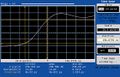
File:Tek 284 1GHz Sine Wave.jpeg|thumb|Tek 284 1 GHz Sine Wave | |||
File:Tek 284 Pulse Train Output.jpeg|200px|thumb|Tek 284 Pulse Train Output | |||
File:Tek 284 Single Pulse OP.jpg|200px|thumb|Tek 284 Pulse Output | |||
File:Tek 284 SN B102219 47ps Pulse on 20cm Air Line.jpg|200px|thumb|Tek 284 Pulse Output | |||
</gallery> | </gallery> | ||
==Components== | |||
{{Parts|284}} | |||
[[Category:Pulse generators]] | [[Category:Pulse generators]] | ||
Latest revision as of 19:30, 17 December 2023

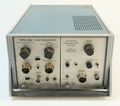
The Tektronix 284 is a pulse generator introduced in July 1967. Its output modes include:
- 70 ps risetime pulse, 200 mV, 50 kHz repetition rate, 1 μs pulse duration (5% duty cycle)
- Sine wave, 1 GHz or 100 MHz, 100 mV
- Square wave, 10 MHz, 1 MHz or 100 kHz, 10 mV, 100 mV, or 1 V
Only one mode can be used at a time. The pulse comes out one output connector. The sine wave and square wave come out another output connector. Both outputs are 50 Ω GR-874.
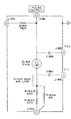
The 284 generates a 1 GHz sinewave using a 2N3478 RF NPN transistor-based oscillator.
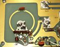
The 284 generates the 70 ps risetime pulse using a 20 mA, 1.5 pF tunnel diode, D180, Tektronix part number 152-0329-00. D180 is mounted inside of a 50 Ω airline (rigid coaxial transmission line with only air between the center conductor and the shell). D180 is in series with the airline's center conductor. One end of the airline contains three resistors for biasing the tunnel diode and terminating the transmission line. The other end of the airline is the GR-874 pulse output connector. For each pulse (every 20 μs):
- the biasing current is switched on, putting D180 close to its peak current
- a capacitively coupled "tripper" applies a short current pulse to D180, causing it to switch to its high-voltage state
- the biasing current is switched off, causing the tunnel diode to fall back to the low-voltage state
The tripper pulse is produced by a snap-off diode. Air gap capacitors couple the tripper pulse to the tunnel diode. These capacitors, C185 and C186, are drawn with dashed lines in the schematic because they are really just stray capacitances. One side of each capacitor is the unconnected center pin of the bulkhead-mount female SMB connectors in the side of the airline. The other side of the capacitor is the conductive tunnel diode mount in the core of the airline.
Modification kit 040-0487-00 changes the times selectable with the lead time switch.
Links
- Zenwizard Studios - Unit I rebuild including Airline and D-180
- Zenwizard Studios - Unit I rebuild including Airline and D-180 testing on Tek 577
Documents Referencing 284
| Document | Class | Title | Authors | Year | Links |
|---|---|---|---|---|---|
| Tekscope 1970 V2 N3 Jun 1970.pdf | Article | Tektronix Signal Sources | 1970 | 2101 • 2901 • 114 • 115 • R116 • 106 • 191 • 284 • 140 |
See Also
- 284-based PPPG
- Tek 284 page at amplifier.cd with detailed internals and repair/cal report
- Tek 284 Repair at shaunmerrigan.info Photos of TD and output waveforms
Pictures
-
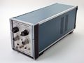
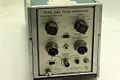
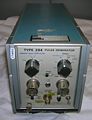
3/4 View
-
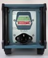
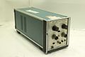
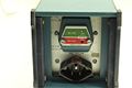
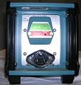
Rear Panel
-

Interior Top
-
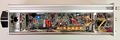
Interior Bottom
-

Interior Left
-

Interior Right
-
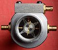
Tunnel diode in housing
-
Oscillator
-
Fast pulse output schematic
-
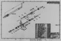
Pulser module drawing
-
-
-

-
-
-
-
284 with 067-0508-00
-

Tek 284 10MHz Square Wave
-

Tek 284 1 GHz Sine Wave
-
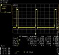
Tek 284 Pulse Train Output
-
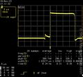
Tek 284 Pulse Output
-
Tek 284 Pulse Output


Components
Some Parts Used in the 284
| Part | Part Number(s) | Class | Description | Used in |
|---|---|---|---|---|
| 2N3478 | 151-0173-00 | Discrete component | NPN RF transistor | 284 |
| SMTD892 | 152-0329-00 | Discrete component | 19 mA, 1.5 pF tunnel diode | 284 • 7T11 • 7T11A |