3A1: Difference between revisions
Jump to navigation
Jump to search
No edit summary |
No edit summary |
||
| (6 intermediate revisions by 3 users not shown) | |||
| Line 1: | Line 1: | ||
{{Plugin Sidebar | {{Plugin Sidebar| | ||
manufacturer=Tektronix |series=560-series scopes |type=3A1 | | |||
summary=Dual trace amplifier plugin | | summary=Dual trace amplifier plugin | | ||
image=3a1 front2.jpg | | image=3a1 front2.jpg | | ||
caption=Type 3A1 front view | | caption=Type 3A1 front view | | ||
designers= | | |||
introduced=1962 | | introduced=1962 | | ||
discontinued=1968 | | discontinued=1968 | | ||
manuals= | manuals= | ||
* [http://bama.edebris.com/download/tek/3a1/3a1.djvu Tektronix 3A1 Manual (DJVU) | * [[Media:070-343.pdf|Tektronix 3A1 Manual 070-343]] (PDF) | ||
* [[Media:Tek 3a1 fcp nov 1963. | * [[Media:070-0343-01.pdf|Tektronix 3A1 Manual 070-0343-01]] (PDF) | ||
* [http://bama.edebris.com/download/tek/3a1/3a1.djvu Tektronix 3A1 Manual @ BAMA] (DJVU) | |||
* [[Media:Tek 3a1 fcp nov 1963.pdf|Tektronix 3A1 Factory Calibration Procedure, November 1963]] | |||
}} | }} | ||
The '''Tektronix Type 3A1''' is a dual-trace amplifier plug-in | The '''Tektronix Type 3A1''' is a 10 MHz dual-trace amplifier plug-in for [[560-series scopes]], [[introduced in 1962]]. | ||
for [[560-series scopes]]. | |||
{{BeginSpecs}} | {{BeginSpecs}} | ||
| Line 18: | Line 19: | ||
{{Spec | Risetime | 35 ns }} | {{Spec | Risetime | 35 ns }} | ||
{{Spec | Input impedance | 1 MΩ // 47 pF }} | {{Spec | Input impedance | 1 MΩ // 47 pF }} | ||
{{Spec | Deflection factor | 10 mV/div to 10 V/div, | {{Spec | Deflection factor | 10 mV/div to 10 V/div, 1−2−5 sequence}} | ||
{{EndSpecs}} | {{EndSpecs}} | ||
Revision as of 10:00, 20 August 2021

The Tektronix Type 3A1 is a 10 MHz dual-trace amplifier plug-in for 560-series scopes, introduced in 1962.
Key Specifications
| Bandwidth | 10 MHz |
|---|---|
| Risetime | 35 ns |
| Input impedance | 1 MΩ // 47 pF |
| Deflection factor | 10 mV/div to 10 V/div, 1−2−5 sequence |
Internals
The input signal passes through compensated attenuators and then into a cathode-follower stage made of two 7586 Nuvistor tubes.
Channel switching in ALTERNATE mode is done using diodes. The output stage that drives the vertical deflection plates of the scope uses a pair of 8233 frame grid power pentode tubes.
Pictures
-
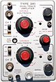
Front view
-
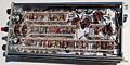
Right side
-
Right side
-

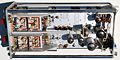
Top view
-

Bottom view
-
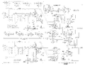
input amplifier schematic


