453
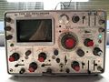
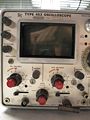
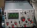
The Tektronix 453 is a portable 50MHz dual-trace oscilloscope introduced in 1966 and produced until the mid-1970's. Initial versions had Nuvistor tubes in the front end as cathode-follower voltage buffers. Later versions used FETs for the same purpose. The vertical amplifier that drives the CRT deflection plates is a cascoded differential amplifier made of NPN transistors. Triggering uses tunnel diodes, with a trigger preamplifier preceding the actual trigger circuit. The 453 is almost entirely solid-state, even in its first version. The only tubes other than the CRT are the 5642 HV rectifiers and a few 8393 Nuvistor triode tubes. Each horizontal deflection plate is driven by a common-emitter amplifier with feedback. The total CRT acceleration is 10kV. The CRT cathode voltage is -2kV and the CRT anode voltage is +8kV. A Tektronix 453 consumes 100 watts power and weighs 29 pounds (13.2kg).
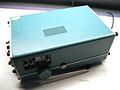
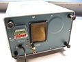
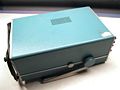
The 453 came with a rigid metal cap that protects the face of the scope while it is in transit. This cap has a compartment for storing probes and accessories. Inside the 453, the electronics are rather densely packed in order for the scope to be compact. The top and bottom cover of the case separate simultaneously using and ingenious clasp. Removing the rear cover exposes the remaining fuses and circuitry.
There are two trigger/sweep units in a 453, thereby enabling delayed sweep mode. There are two delayed sweep modes: "A sweeps after B" and "A triggerable after B".
The 453 uses Nuvistors. The 453A, introduced in 1971, replaced the Nuvistors with transistors, extended the bandwidth to 60MHz, increased the graticule from 6cm x 10cm to 8cm x 10cm, and introduced a mixed-sweep mode. Mixed-sweep mode starts the sweep at one sweep time/div rate and then, at some selectable horizontal point, switches to a different sweep time/div rate.
The 453A Mod 127C appears in the 1971 Television Products Catalog, with the description:
With the Mod 127C, and Internal TV Sync Separator circuit permits stable internal line or Field-rate triggering from displayed composite video or composite sync waveforms. External /10 trigger sources are replaced by Internal TV Sync positions providing Line sync pulses to the B Sweep circuit and either Field or Line sync pulses to the A sweep circuit.
-

-
-

-
-
-
-
-
453


