500-series plug-in connector: Difference between revisions
Jump to navigation
Jump to search
No edit summary |
No edit summary |
||
| Line 27: | Line 27: | ||
|- | |- | ||
! scope="row" | 4 | ! scope="row" | 4 | ||
| Trigger - | | Trigger - <br> 544, 546, 547, 549, late 555s, and 556 | ||
|- | |- | ||
! scope="row" | 5 | ! scope="row" | 5 | ||
| Trigger + | | Trigger + <br> 544, 546, 547, 549, late 555s, and 556 | ||
|- | |- | ||
! scope="row" | 6 | ! scope="row" | 6 | ||
| Sawtooth (on 556 only) | | Sawtooth (on 556 only?) | ||
|- | |- | ||
! scope="row" | 7 | ! scope="row" | 7 | ||
Revision as of 10:05, 25 July 2014
500-series scopes (53x, 54x, and 55x) and 127, 132, 133 have bays that take letter-series and 1-series plug-ins which typically control the vertical axis of the display. Two exceptions are the 555 and the 536. The 555 takes four plug-ins: Two letter-series and 1-series plug-ins control vertical deflection of the two beams. Two 555-specific timing/sweep plug-ins (21, 22, 21A, 22A) control the horizontal deflection of the two beams. The 536 takes two letter-series or 1-series plug-ins; the left one controls vertical deflection and the right one controls horizontal deflection. 580-series scopes use their own plug-ins.
The pinout on the connector is as follows:
| Pin number | Function |
|---|---|
| 1 | Signal + |
| 2 | GND |
| 3 | Signal - |
| 4 | Trigger - 544, 546, 547, 549, late 555s, and 556 |
| 5 | Trigger + 544, 546, 547, 549, late 555s, and 556 |
| 6 | Sawtooth (on 556 only?) |
| 7 | Alt Timebase sync (on 547 only) |
| 8 | Multi-Trace Sync |
| 9 | -150 V DC |
| 10 | +100V DC |
| 11 | +225V DC |
| 12 | +350V DC |
| 13 | 6.3V AC relative to pin 14 |
| 14 | 6.3V AC relative to pin 13 |
| 15 | +75V DC |
| 16 | Multi-Trace Sync |
-
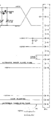
pinout shown in 1A2 schematic
-
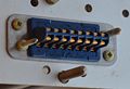
front pins
-
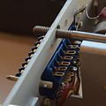
rear soldering lugs


