511

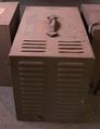
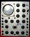
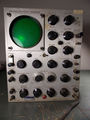
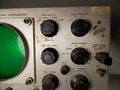
The 511 was Tek's first oscilloscope, introduced in June 1947, but the second product (the first was the Type 101 Video Calibrator). A revised version, the 511A, was introduced in 1950. Howard Vollum was directly involved with the design of the 511.
Specifications
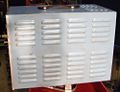
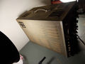
The 511A does not have response down to DC − frequency range is specified as 10 Hz to 10 MHz. There is also a 511AD, where the "D" in the model number indicates that it has a L-C delay line. The 511 weighs 65 pounds (29 kg) and consumes 180 W. The 511A weighs 50 pounds (23 kg) and consumes 230 W. please add
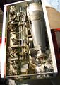
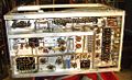
Internals
The 511 and 511A were normally furnished with P1 phosphor. P7 and P11 were optional, at no extra charge.
The 511/511A uses a standard CRT, the 5CP1A (P1), 5CP7A (P7) or 5CP11A (P11) below S/N 5100, the 5ABP from 5100 up. The vertical output of the 511A is a pair of 6AG7 tubes, AC-coupled to the vertical deflection plates.
Neither the 511 nor the 511A has a thermal cutoff. The 511AD was available through 1953.
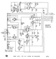
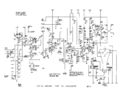
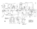
The 511 was produced with serial numbers 101 to 454. The 511A has serial numbers 455 and up. The main difference between the 511 and the 511A is the power supply. In the 511 there are two power transformers, T1 and T2, both operating on 60 Hz mains power with their primaries in parallel. T1 produces the CRT anode and cathode voltages, as well as various other regulated and unregulated voltages. The CRT cathode and anode voltages in the 511 are simply rectified voltages from the secondary of T1. The lack of regulation means that variations in mains voltage results in variation of deflection sensitivity.
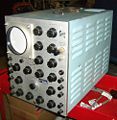
In the 511A, the CRT cathode and anode voltages are produced by a 2 kHz oscillator that is powered by the 511A's +225 VDC regulated supply. This results in vertical deflection calibration that is independent of mains voltage.
The 511 and 511A use a 6AL5 tube (V3) as the disconnect diode for the sweep.
There was an option that added a 1 μs marker generator.
Delay
The Tektronix Type 1-AD-25 delay was available as a factory option for the 511. With the delay, the scope is a 511-AD. The delay is composed of 24 L-C sections. Even when ordered without the delay, the 511's chassis was pre-drilled for the delay so that it could be added later, in the field, without drilling. The delay could be switched in and out of the signal path, presumably to avoid the slight signal degradation the delay causes.
History
Tektronix engineer Frank Hood recollects:
My first assignment was to build or modify some special instruments for Bonneville Power. They wanted a device that would detect and record any lightning strikes or arc-overs on the high voltage power lines running between Vancouver, Wash. and other cities such as Longview, Spokane, etc. They wanted to detect each event, in a fraction of a millionth of a second, then to send a pulse of energy down the defective line and measure the time it took to return, (this was an application much like radar). They wanted markers displayed at each mile and fraction of a mile so that they could determine the exact location of the fault. They needed to record a photographic image for latter study. Two or more such instruments were built. We called these Type 511B. They worked very well and were used for several years.
John Addis says:
The 511 was indeed somewhat crude. The vaunted calibrator which Vollum introduced to give people the sense that you could make real measurements is actually just a 60 Hz sine wave off the power transformer, not even a square wave, so it is completely unregulated. Fortunately for Vollum, both the calibrator and the CRT HV are unregulated. When the line voltage goes down, the scope sensitivity goes up (reduced HV makes beam converge less after plates). So the displayed calibrator amplitude is not very sensitive to line voltage.
Links
Pictures
-

511
-
511
-
511
-
511
-
511A
-
511A
-
511A
-
511A
-
511A
-

-
511A
-
511A
-
511A
-

Vollum scope - Electronics Magazine, April 1948
-
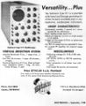
511 Ad from September 1948
-
511AD
-
511AD
-
511AD
-
511AD


Some Parts Used in the 511
| Part | Part Number(s) | Class | Description | Used in |
|---|---|---|---|---|
| 0C3 | 154-0002-00 | Gas Discharge Tube (Voltage regulator) | 105 V voltage reference | 511 |
| 0D3 | 154-003 • 154-0003-00 | Gas Discharge Tube (Voltage regulator) | 153 V voltage reference | 511 • 511A • 513 • 514 |
| 2X2 | 154-0085-00 | Vacuum Tube (Dual Rectifier) | dual rectifier | 511 |
| 5CP | 154-062 • 154-0062-00 | CRT | 5" CRT with post-deflection acceleration | 511 • 511A |
| 5U4 | 154-086 • 154-0086-00 | Vacuum Tube (Dual Rectifier) | dual rectifier | 511 |
| 6AC7 | 154-011 • 154-0011-00 | Vacuum Tube (Pentode) | RF pentode | 511 • 511A |
| 6AG7 | 154-012 • 154-0012-00 | Vacuum Tube (Pentode) | 9 Watt power pentode | 104 • 104A • 105 • 112 • 511 • 511A • 512 • 513 • 514 • 517 • 517A • 524 |
| 6AL5 | 154-016 • 154-0016-00 • 154-0038-00 | Vacuum Tube (Dual Diode) | high-perveance dual diode | 163 • 181 • 190 • 1M1 • 310 • 310A • 315 • 316 • 317 • 3B1 • 3B1S • 3B2 • 3B3 • 3B5 • 502 • 502A • 503 • 511 • 511A • 512 • 516 • 517 • 517A • 524 • 526 • 535 • 535A • 545 • 545A • 549 • 551 • 565 • 570 • 581 • 581A • 585 • 585A • C • T • Telequipment D56 • Telequipment S52 |
| 6AU6 | 154-0022-00 • 157-0073-00 • 157-0059-00 • 154-0284-00 | Vacuum Tube (Pentode) | RF pentode | 107 • 160 • 181 • 190 • 60 • 2A60 • 72 • 3A72 • 3C66 • 310 • 310A • 316 • 317 • 360 • 502 • 502A • 506 • 511 • 511A • 512 • 513 • 516 • 517 • 517A • 524 • 526 • 529 • RM529 • 531 • 531A • 535 • 536 • 545 • 545A • 546 • 547 • 549 • 555 • 561 • 561A • 561S • 564 • 565 • 567 • 570 • 575 • 581 • 581A • 585 • 585A • 80 • C • CA • Q |
| 6C4 | 154-029 • 154-0029-00 | Vacuum Tube (Triode) | VHF triode | 190 • 3B2 • 507 • 511 • 511A • 517 • 517A • Chemtrix 205 |
| 6J6 | 154-032 • 154-0032-00 | Vacuum Tube (Dual Triode) | high-frequency dual triode | 104 • 104A • 161 • 511 • 511A • 512 • 517 • 517A |
| 6L6 | 154-087 • 154-0087-00 | Vacuum Tube (Pentode) | beam power pentode | 511 |
| 6SJ7 | 154-088 • 154-0088-00 | Vacuum Tube (Pentode) | Pentode | 511 |
| 6V6 | 154-089 • 154-0089-00 | Vacuum Tube (Pentode) | 12-watt beam power pentode | 511 |
| 6X5 | 154-090 • 154-0090-00 | Vacuum Tube (Dual Rectifier) | dual rectifier | 511 |
| NE-2 | 150-002 • 150-0002-00 | Gas Discharge Tube (Neon lamp) | Neon lamp | 511 • 511A • 581 • 581A • 585 • 585A • 545A • TU-4 |