520: Difference between revisions
m (→Pictures) |
No edit summary |
||
| (6 intermediate revisions by 3 users not shown) | |||
| Line 5: | Line 5: | ||
|series= | |series= | ||
|summary=NTSC/PAL vectorscope | |summary=NTSC/PAL vectorscope | ||
|image= | |image=520A_wTrace.jpg | ||
|caption= | |caption=520A vectorscope | ||
|introduced=1967 | |introduced=1967 | ||
|discontinued=(?) | |discontinued=(?) | ||
|designers= | |designers=Phil Crosby;Ron Olson | ||
|manuals= | |manuals= | ||
* [[Media:070-0639-02.pdf|Tektronix 520 Manual]] | * [[Media:070-0639-02.pdf|Tektronix 520 Manual]] | ||
* [[Media:070-1709-00.pdf|Tektronix 520A Manual]] | * [[Media:070-1709-00.pdf|Tektronix 520A Manual]] | ||
* [[Media:Tek 520 pal fcp sept 1968.pdf | Tektronix 520 PAL Factory Calibration Procedure, September 1968 ( | * [[Media:Tek 520 pal fcp sept 1968.pdf | Tektronix 520 PAL Factory Calibration Procedure, September 1968]] (needs OCR) | ||
* [https://w140.com/tek_520_cat.pdf Tektronix 520 Entry in 1968 Catalog | * [https://w140.com/tek_520_cat.pdf Tektronix 520 Entry in 1968 Catalog] | ||
}} | }} | ||
The '''Tektronix 520''' is a vectorscope [[introduced in 1967]]. | The '''Tektronix 520''' is a vectorscope [[introduced in 1967]]. Versions were made for NTSC and for PAL. | ||
[[Phil Crosby]] was the project lead and designed the demodulation circuitry. [[Ron Olson]] designed the sweep. | |||
The HV oscillator's power transistor is mounted to the rear panel. | |||
Since its collector has 40 kHz with tens of volts peak-to-peak a decision was made to add metal plating to the transistor's Bakelite cover to prevent EMI. | |||
Unexpectedly, the outgassing from the Bakelite caused the metal plating to blister, which shorted the collector to the case. | |||
When this problem was discovered, the metal plating was removed from the design. In hindsight, the designers didn't believe the plating was necessary in the first place. | |||
{{MissingSpecs}} | {{MissingSpecs}} | ||
==Pictures== | ==Pictures== | ||
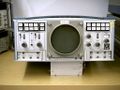
====520==== | ====520==== | ||
<gallery> | <gallery> | ||
Tek 520 cat.jpg | Tek 520 cat.jpg | 520 catalog image | ||
Tek type r520.jpg | Tek type r520.jpg | ||
Tek 520 pal.jpg|520 PAL version | Tek 520 pal.jpg|520 PAL version | ||
| Line 30: | Line 38: | ||
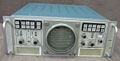
====520A==== | ====520A==== | ||
<gallery> | <gallery> | ||
520A_wTrace.jpg | |||
520A_Front.jpg | 520A_Front.jpg | ||
R520a front.jpg | R520a front.jpg | ||
| Line 47: | Line 56: | ||
</gallery> | </gallery> | ||
{{Parts|520}} | |||
[[Category:TV vectorscopes]] | [[Category:TV vectorscopes]] | ||
Revision as of 11:42, 10 July 2022

The Tektronix 520 is a vectorscope introduced in 1967. Versions were made for NTSC and for PAL.
Phil Crosby was the project lead and designed the demodulation circuitry. Ron Olson designed the sweep.
The HV oscillator's power transistor is mounted to the rear panel. Since its collector has 40 kHz with tens of volts peak-to-peak a decision was made to add metal plating to the transistor's Bakelite cover to prevent EMI. Unexpectedly, the outgassing from the Bakelite caused the metal plating to blister, which shorted the collector to the case. When this problem was discovered, the metal plating was removed from the design. In hindsight, the designers didn't believe the plating was necessary in the first place.
Key Specifications
- please add
Pictures
520
-

520 catalog image
-
-
520 PAL version


520A


Some Parts Used in the 520
| Part | Part Number(s) | Class | Description | Used in |
|---|---|---|---|---|
| T5201 | 154-0513-00 • 154-0513-01 • 154-0513-02 • 154-0513-03 | CRT | CRT with special graticule | 520 • 521 • 522 |