555: Difference between revisions
m (Delayed Trigger/H Plug-in Details) |
(→Power Supply and Filament Supply Regulator: reformulated to eliminate repetition) |
||
| Line 56: | Line 56: | ||
== Power Supply and Filament Supply Regulator == | == Power Supply and Filament Supply Regulator == | ||
The external power supply unit generates all the B+ Voltages ( | The external power supply unit generates all the B+ Voltages (–150, +100, +225, +330, +350 and +500 V) required by the indicator unit. | ||
These are fed to the indicator unit through the interconnect cable. | |||
There are two transformers inside the power supply unit – one to generate heater voltages (except for the tubes noted below), the other to generate all the B+ plate voltages. | |||
The heater/filament supply for all the tubes inside the indicator unit are generated by a transformer inside the indicator unit. | The heater/filament supply for all the tubes inside the indicator unit are generated by a transformer inside the indicator unit. | ||
A saturable inductor, located in the power supply unit, is connected in series with its primary as the control element of an AC regulator circuit. | |||
One 6.3 V winding from the indicator unit filament transformer is fed back through the interconnection cable (part number [[012-032]]) | |||
to supply heaters of specific tubes in the power supply unit (V624, V634, V664, V684, V694). Moreover, a regulator Tube (2AS-15, a | |||
Temperature Limited Diode) is used to sense this filament voltage and derive a control DC current through the saturable inductor, | |||
thereby signal closing the control loop. | |||
One of the consequences of this scheme is that it the power supply unit will not energize the plate voltages (except +100 V) | |||
without the indicator unit connected, because | |||
* the 12AX7 comparators and 6AU6 error amplifiers are heated from the indicator unit, so the main series pass tubes (6080s and 12B4s) are not driven even though they are heated from a transformer in the power supply unit; | |||
* The primary of the plate voltage transformer inside the power supply unit is looped via the thermal cutout in the indicator unit, i.e. the plate voltage transformer in the power supply will not get power unless the indicator unit is attached. | |||
Even if one were to power up the power supply itself by bypassing the thermal cut-out and applying local heater voltages to the tubes normally supplied by the indicator unit, the power supply will not regulate as the design employs shunting resistors across the series pass tubes, and can therefore not regulate without a load. | |||
== Vertical Amplifier == | == Vertical Amplifier == | ||
Revision as of 04:12, 28 November 2019

The Tektronix Type 555, nicknamed "Triple Nickel", is a dual-beam CRT oscilloscope introduced by Tektronix in
1959 and made until the late 1960's, when it was replaced by the 556.
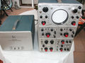
The system is split across two cabinets, the main indicator unit and the external power supply unit. The power supply unit contains the main transformer, rectifiers and regulators for all of the voltages except the filament and CRT HV supplies. The filament and CRT HV voltages are generated in the 555 indicator unit.
The Tektronix 555 takes two letter-series or 1-series vertical plug-ins
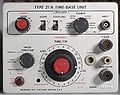
Type 21 and 22 Timebases
The 555 uses special horizontal plug-ins that contain the trigger and sweep. Early instances of the 555 came with the 21 and 22 horizontal plug-ins.
Type 21 is suggested for the upper beam and type 22 is suggested as the lower beam time base, as type 22 contains delayed trigger, and only the lower beam horizontal section is provided with delayed trigger pickup circuitry. The Delay multiplier control pot is also provided on the lower beam section.
A rigid plug-in extension for the timebases (part number 013-013) was included with every 555.
Type 21A and 22A Timebases
Later instances came with the 21A and 22A horizontal plug-ins, which use tunnel diodes for triggering. Delayed triggering is supported. Since the 555 is a dual-beam scope, it is also possible to start one of the sweeps while the other beam is sweeping. The upper-beam sweep and lower-beam sweeps are, in fact, totally independent.
Power Supply and Filament Supply Regulator
The external power supply unit generates all the B+ Voltages (–150, +100, +225, +330, +350 and +500 V) required by the indicator unit. These are fed to the indicator unit through the interconnect cable.
There are two transformers inside the power supply unit – one to generate heater voltages (except for the tubes noted below), the other to generate all the B+ plate voltages.
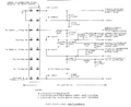
The heater/filament supply for all the tubes inside the indicator unit are generated by a transformer inside the indicator unit. A saturable inductor, located in the power supply unit, is connected in series with its primary as the control element of an AC regulator circuit. One 6.3 V winding from the indicator unit filament transformer is fed back through the interconnection cable (part number 012-032) to supply heaters of specific tubes in the power supply unit (V624, V634, V664, V684, V694). Moreover, a regulator Tube (2AS-15, a Temperature Limited Diode) is used to sense this filament voltage and derive a control DC current through the saturable inductor, thereby signal closing the control loop.
One of the consequences of this scheme is that it the power supply unit will not energize the plate voltages (except +100 V) without the indicator unit connected, because
- the 12AX7 comparators and 6AU6 error amplifiers are heated from the indicator unit, so the main series pass tubes (6080s and 12B4s) are not driven even though they are heated from a transformer in the power supply unit;
- The primary of the plate voltage transformer inside the power supply unit is looped via the thermal cutout in the indicator unit, i.e. the plate voltage transformer in the power supply will not get power unless the indicator unit is attached.
Even if one were to power up the power supply itself by bypassing the thermal cut-out and applying local heater voltages to the tubes normally supplied by the indicator unit, the power supply will not regulate as the design employs shunting resistors across the series pass tubes, and can therefore not regulate without a load.
Vertical Amplifier
The Tektronix 555 has a six-section differential distributed vertical output amplifier made of 6DK6 tubes. It is the same as the vertical output amplifier inthe 551 and the 545A. An L-C delay line is between the vertical output amplifier and the CRT vertical deflection plates for each channel.
Architecturally, the 555, with its four plug-ins, is similar to the 7844.
CRT Circuit
The CRT circuit in the 555 is really two separate modules. It is split between two internal metal enclosures, each one containing a high voltage transformer and associated tubes. The lower beam HV power supply is based on transformer T901 and produces:
- CRT anode voltage: +8,650 V
- lower beam CRT cathode voltage: -1,350 V
- lower beam CRT control grid (blanking) voltage: floating, -1,500 V
The upper beam HV power supply is based on T801 and produces:
- upper beam CRT cathode voltage: -1,350 V
- upper beam CRT control grid (blanking) voltage: floating, -1,500 V
Rectification and voltage multiplication is performed by a total of six 5642 rectifier tubes. Each of the two HV power supplies is independently regulated using a two-stage common-cathode amplifier based on a 12AU7 dual triode. The oscillator tube is a 6CZ5 power pentode.
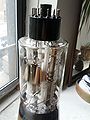
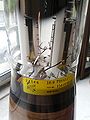
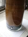
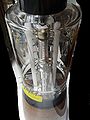
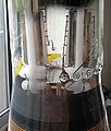
The 555 uses the T5550 CRT.
Links
- Tektronix 555 in operation @ YouTube
- Tektronix 555 @ barrytech.com
- Tektronix 555 @ radiomuseum.org
- Greg's 555 - lots of photos
Pictures
-
-
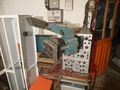
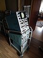
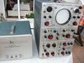
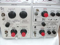
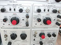
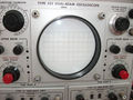
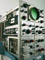
front view: two timing plug-ins on top and two vertical plug-ins on bottom
-
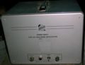
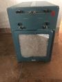
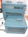
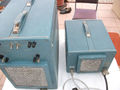
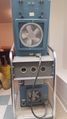
external power supply
-
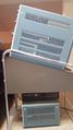
left side view
-
right side view
-
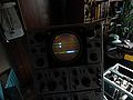
top view
-
Top with with HV Cover off
-

555 with P11-option
-
555 with P7-option (fast blue and slow green Phosphor)
-
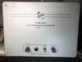
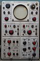
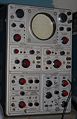
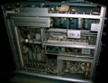
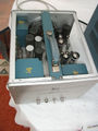
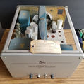
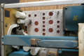
555 Power Supply - Front
-
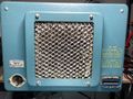
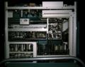
555 Power Supply - Rear
-
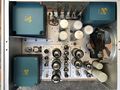
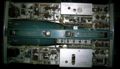
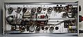
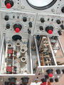
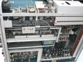
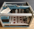
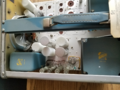
555 Power Supply Internals - Top
-
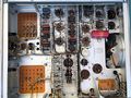
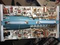
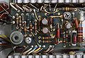
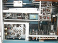
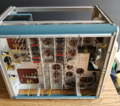
555 Power Supply Internals - Bottom
-
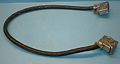
Power interconnect, part number 012-032
-
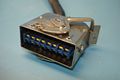
Power interconnect, part number 012-032
-
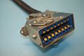
Power interconnect, part number 012-032
-
timebase interconnect
-
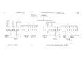
555 block diagram
-
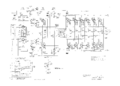
lower beam vertical amplifier
-
power interconnect
-
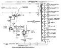
heater regulator
-
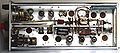
Type 21 trigger
-
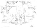
block diagram
-
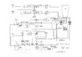
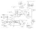
CRT circuit
-
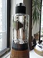
CRT
-
CRT
-
CRT
-
CRT
-
CRT
-
CRT
-
22A front
-
22A TD trigger board
-

22A top
-
22A bottom
-
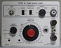
21 front
-
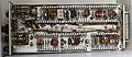
21 top
-

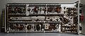
21 bottom
-

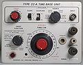
22 front
-
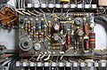
22 top
-
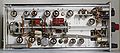
22 bottom
-
21A front
-

21A top
-
21 bottom
-
21A TD trigger board
-
timebase plug-in extender, part number 013-013
-

-
-
555 rear
-
-
-
-
-
-
-
-
-
-
-
-

-
555 photo from technikum29.de
-
555 power supply
-
555 power supply
-
555 power supply
-
555 power supply
-
555 power supply
-
-
-