560 Series plug-in interface: Difference between revisions
No edit summary |
No edit summary |
||
| Line 5: | Line 5: | ||
560-series plug-ins are designed to drive the [[CRT]]'s deflection plates directly. The impedance seen by the differential | 560-series plug-ins are designed to drive the [[CRT]]'s deflection plates directly. The impedance seen by the differential | ||
signal of the plug-in looking into the mainframe is typically 14.3 pF and has no resistive component. The mainframe | signal of the plug-in looking into the mainframe is typically 14.3 pF and has no resistive component. The mainframe | ||
contains trimmer capacitors to standardize this | contains trimmer capacitors to standardize this capacitance. | ||
The deflection sensitivity of the mainframe to differential deflection signals at the plug-in connector is about | The deflection sensitivity of the mainframe to differential deflection signals at the plug-in connector is about | ||
Latest revision as of 04:30, 26 September 2018

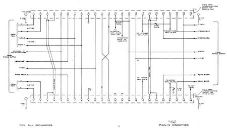
The plug-in interface of the 560-series scopes is a single 24-pin Amphenol connector per slot (horizontal/vertical).
560-series plug-ins are designed to drive the CRT's deflection plates directly. The impedance seen by the differential signal of the plug-in looking into the mainframe is typically 14.3 pF and has no resistive component. The mainframe contains trimmer capacitors to standardize this capacitance.
The deflection sensitivity of the mainframe to differential deflection signals at the plug-in connector is about 19.5 V/div for the vertical and 18.5 V/div for the horizontal plates. The sensitivity is not standardized, it depends on the CRT and high voltage. This means that when plug-ins are swapped between mainframes, they need to be recalibrated.
Pin-out
| Pin | Function | Comment |
|---|---|---|
| 1 | 6.3 VAC | 6 A capacity in 561, dedicated winding per slot |
| 2 | 6.3 VAC | return for pin 1 |
| 3 | multi-trace sync pulse | 50 Ω coax between slots, center conductor on right slot, screen on left slot |
| 4 | multi-trace sync pulse | 50 Ω coax between slots, screen on right slot, center conductor on left slot |
| 5 | −12.2 V ground return | |
| 6 | +420 V unreg. via 2 kΩ | from +300 V regulator input, regulator bypass resistor in plug-in to pin 10 |
| 7 | 117 VAC | from mains transformer primary (power line) |
| 8 | 117 VAC | return for pin 8 |
| 9 | chassis ground | |
| 10 | +300 V reg. | |
| 11 | trigger signal out (V) | to pin 12 on other slot |
| 12 | trigger signal in (H) | from pin 11 on other slot |
| 13 | blanking | to blanking deflection plate on CRT, 560 kΩ pull-up to 125 V in 561 (NC on left slot) |
| 14 | intensifying | to CRT grid circuit (NC on left slot) |
| 15 | +125 V reg. | |
| 16 | −12.2 V reg. | |
| 17 | −deflection plate | left H on right slot, lower V on left slot |
| 18 | plug-in interconnect | 50 Ω coax between slots, center conductor |
| 19 | plug-in interconnect | 50 Ω coax between slots, screen |
| 20 | +210 V unreg. via 2 kΩ | from +125 V regulator input, regulator bypass resistor in plug-in to pin 15 |
| 21 | +deflection plate | right H on right slot, upper V on left slot; ~19.5 V/div (V), 18.5 V/div (H) |
| 22 | +75 V unreg. via 2 kΩ | from −100 V regulator input, regulator bypass resistor in plug-in to ground |
| 23 | −100 V reg. | |
| 24 | chopped blanking | to CRT cathode in left slot, NC in right slot; grounded in 1-ch amplifiers, NC in timebases |
Pin group function legend
DC power AC and heater power Deflection and Trigger Signals Control Signals