| Peak Current (Step Generator in Pulsed Steps Mode)
| style="text-align: center;" | At least 20 A
| style="text-align: center;" | At least 4 A
| style="text-align: center;" | At least 1 A
| style="text-align: center;" | At least 0.2 A
|-
|
| Minimum Series Resistance
| style="text-align: center;" | 0.3 Ω
| style="text-align: center;" | 6.5 Ω
| style="text-align: center;" | 140 Ω
| style="text-align: center;" | 3 kΩ
|-
|
| Maximum Series Resistance
| style="text-align: center;" | 65 kΩ
| style="text-align: center;" | 1.4 MΩ
| style="text-align: center;" | 6.5 MΩ
| style="text-align: center;" | 6.5 MΩ
|-
|
| Series Resistances Available
| colspan="4" | 0.3 Ω, 1.4 Ω, 6.5 Ω, 30 Ω, 140 Ω, 650 Ω, 3 kΩ, 14 kΩ, 65 kΩ, 300 kΩ, 1.4 MΩ, and 6.5 MΩ, all within 5% or 0.1 Ω.
|-
|
| Peak Power Watts Settings
| colspan="4" | 0.1 W, 0.5 W, 2.2 W, l0 W, 50 W and 220 W. Derived from nominal peak open circuit collector voltages and nominal series resistance values at nominal line voltage.
|-
|
| Safety Interlock
| colspan="4" | When MAX PEAK VOLTS switch is set to either 75, 350 or 1500, a protective box must be in place over test terminals and its lid closed before voltage can be applied. Amber light on indicates interlock is open & Red light on indicates voltage is being applied to test terminals.
|-
|
| Looping Compensation
| colspan="4" | Cancels stray capacitance between collector test terminal and ground in Standard Test Fixture and all Standard Test Fixture Accessories.
|}
===Step Generator===
{| class="wikitable"
! colspan="2" | Accuracy (Current or Voltage Steps, lncluding Offset)
|-
|
| Incremental Accuracy
| Within 5% between any two steps, without .1 X STEP MULT button pressed; within 10% with .1 X STEP MUL T button pressed.
|-
|
| Absolute Accuracy
| Within 2% of total output, including any amount of offset, or 1% of AMPLITUDE switch setting, whichever is greater.
|-
! colspan="2" | Step (Current or Voltage) Amplitudes
| One times or 0.1 times (with .1 X STEP MUL T button pressed) the AMPLITUDE switch setting.
|-
! colspan="2" | OFFSET MULT Control Range
| Continuously variable from 0 to 10 times AMPLITUDE switch setting, either aiding or opposing the step generator polarity.
|-
! colspan="2" | Current Mode
|
|-
|
| AMPLITUDE Switch Range
| 200 mA to 50 nA, in 1-2-5 sequence.
|-
|
| Maximum Current (Steps and Aiding Offset)²
| 20 times AMPLITUDE switch setting, except 10 times switch setting when switch is set to 200 mA, and 15 times switch setting when the switch is set to 100 mA.
|-
|
| Maximum Voltage (Steps and Aiding Offset)
| At least 10 V.
|-
|
| Maximum Opposing Offset Current
| Whichever is less: 10 times AMPLITUDE switch setting, or between 10 mA and 20 mA.
|-
|
| Maximum Opposing Voltage
| Between 1 V and 3 V.
|-
|
| Ripple Plus Noise
| 0.5% or less of AMPLITUDE switch setting or 1 nA, peak to peak.
|-
! colspan="2" | Voltage Mode
|
|-
|
| AMPLITUDE Switch Range
| 50 mV to 2 V, in 1-2-5 sequence.
|-
|
| Maximum Voltage (Steps and Aiding Offset)
| 20 times AMPLITUDE switch setting.
|-
|
| Maximum Current (Steps and Aiding Offset)
| At least 2 A at 10 V or less, decreasing linearly to 10 mA at 40 V.
|-
|
| Short Circuit Current Limiting (Steps and Aiding Offset)
| 20 mA, 100 mA, 500 mA, +100%-0%; 2 A +50%-0%; as selected by CURRENT LIMIT switch.
|-
|
| Maximum Opposing Offset Voltage
| 10 times AMPLITUDE switch setting.
|-
|
| Maximum Opposing Current
| Limited at between 5 mA and 20 mA
|-
|
| Ripple Plus Noise
| 0.5% or less of AMPLITUDE switch setting, or 2 mV, peak to peak.
|-
! colspan="2" | Step Rates
| (Front panel RATE button labels in parentheses.) 1 times (.5X), 2 times (NORM) and 4 times (2X) line frequency. Steps occur at zero collector voltage when .5X or NORM RATE buttons are pressed. and also at peak voltage when 2X RATE button is pressed. Steps occur at collector voltage peak and at normal rate when .5X and 2X RATE buttons are pressed together.
|-
! colspan="2" | Pulsed Steps
| Pulsed steps 80 μS wide within +20%, -5% or 300 μS wide within +5%, -15% produced whenever one of the PULSED STEPS buttons is pressed. Pulsed steps can be produced only at normal and .5 times normal rates. Collector Supply mode automatically becomes DC when either the 300 μS or 80 μS PULSED STEPS button is pressed unless POLARITY switch is set to AC. If the 300 μS and 80 μS PULSED STEPS buttons are pressed together, 300 μS pulsed steps are produced, but collector supply mode does not change.
|-
! colspan="2" | Steps and Offset Polarity
| Corresponds with collector supply polarity (positive going when POLARITY switch is set to AC) when the POLARITY INVERT button is released. Is opposite collector supply polarity (negative-going in AC) when either the POLARITY INVERT button is pressed or the Lead Selector switch is set to BASE GROUNDED. If Lead Selector switch is set to BASE GROUNDED, POLARITY INVERT button has no effect on steps and offset polarity.
|-
! colspan="2" | Step Families
| Repetitive families of characteristic curves generated with REP STEP FAMILY button pressed. Single family of characteristic curves generated each time SINGLE STEP FAMILY button is pressed.
|-
! colspan="2" | Number of Steps
| Ranges from 1 to 10 as selected by the NUMBER OF STEPS switch. For zero steps, press SINGLE STEP FAMILY button.
|}
===Display Amplifiers===
{| class="wikitable"
! colspan="6" | Display Accuracies (% of Highest On-Screen Value)
|-
| colspan="2" |
| colspan="3" | Display magnified (DISPLAY OFFSET Selector switch set to either VERT X10 or HORIZ X10) and offset between
| colspan="4" style="text-align: center;" | 50 mV /division to 200 V /division in 1-2-5 sequence
|-
|
| Horizontal Base Volts
| colspan="4" style="text-align: center;" | 50 mV /division to 2 V/division in 1-2·5 sequence.
|-
|
| Horizontal Base Volts Input Impedance
| colspan="4" style="text-align: center;" | At least 100 MΩ with HORIZONTAL switch set to 50 mV, 100 mV and 200 mV BASE; 1 MΩ within 2% with switch set to .5 V, 1 V and 2V.
| colspan="4" style="text-align: center;" | 1% or less, or the following depending on setting of MAX PEAK VOLTS switch:
|-
| colspan="2" |
| style="text-align: center;" | 15
| style="text-align: center;" | 75
| style="text-align: center;" | 350
| style="text-align: center;" | 1500
|-
|
| Vertical Collector
| style="text-align: center;" | 1 μA
| style="text-align: center;" | 1 μA
| style="text-align: center;" | 2 μA
| style="text-align: center;" | 5 μA
|-
|
| Vertical Emitter
| style="text-align: center;" | 1 nA
| style="text-align: center;" | 1 nA
| style="text-align: center;" | 2 nA
| style="text-align: center;" | 5 nA
|-
|
| Horizontal Collector
| style="text-align: center;" | 5 mV
| style="text-align: center;" | 5 mV
| style="text-align: center;" | 20 mV
| style="text-align: center;" | 200 mV
|-
|
| Horizontal Base
| style="text-align: center;" | 5 mV
| style="text-align: center;" | 5 mV
| style="text-align: center;" | 5 mV
| style="text-align: center;" | 5 mV
|-
! colspan="2" | Calibration Check
| colspan="4" | With DISPLAY OFFSET Selector switch set to NORM (OFF), spot is deflected 10 divisions both vertically and horizontally within 1.5% whenever the CAL button is pressed.
With DISPLAY OFFSET Selector switch set to X10 MAGNIFIER (either axis) the calibration spot is within 0.5% of zero spot (previously set to CRT graticule center) when CAL button is pressed.
|-
! colspan="2" | Vertical and Horizontal Position Controls
| colspan="4" | Coarse positioning in 5 division increments within 0.1 division; continuous fine positioning over at least 5 divisions for each coarse position.
|-
! colspan="2" | Display Offset
| colspan="4" | Vertical or Horizontal offset of display centerline value up to 10 divisions in 21 half division steps.
|-
! colspan="2" | Display Positioning Accuracy Using POLARITY Switch
| colspan="4" style="text-align: center;" | Spot positioning with change in POLARITY switch setting (using AC position as reference), within 0.1 division of:
| colspan="4" | Calibrated area of 10 divisions by 10 divisions; 12 usable divisions horizontally ( 1 division equals 1cm).
|-
|
| Typical Accelerating Potential
| colspan="4" | 4000 V
|-
! Readouts
| colspan="5" | Automatic digitally lighted display. Readout is automatically blanked if readings would be outside the available ranges or would give erroneous display.
|-
|
| PER VERT DIV
| colspan="4" | 1 nA to 20 A calculated from VERTICAL switch setting, DISPLAY OFFSET Selector switch setting and MODE switch setting (or X 10 Vertical Interface Input).
|-
|
| PER HORZ DIV
| colspan="4" | 5 mV to 200 V calculated from HORIZONTAL switch setting and DISPLAY OFFSET Selector switch setting.
|-
|
| PER STEPS
| colspan="4" | 5 nA to 2A and 5 mV to 20 V calculated from AMPLITUDE switch setting and .1X STEP MULT button position (or X10 Step Interface Input).
|-
|
| ß or Gm PER DIV<br />
| colspan="4" | 1 µ to 500 k calculated from VERTICAL switch setting, DISPLAY OFFSET Selector switch setting, AMPLITUDE switch setting, .1 X STEP MULT button position, X10 Vertical Interface Input and X10 Step Interface Input.
|}
===Power Requirements===
{| class="wikitable"
|-
! Power Connection
| colspan="5" | This instrument is designed for operation from power source with its neutral at or near ground (earth) potential. It is not intended for operation from two phases of multi-phase system, or across legs of single-phase, three wire system. It is provided with a three-wire power cord with three-terminal polarized plug for connection to the power source. Third wire is directly connected to instrument frame, and is intended to ground the instrument to protect operating personnel, as recommended by national and international safety codes.
|- style="text-align:center;"
! colspan="2" | Line Voltage Range Setting
| colspan="2" | 115 VAC
| colspan="2" | 230 VAC
|- style="text-align:center;"
| colspan="2" style="text-align:right;" | Low
| colspan="2" | 90 V to 110 V
| colspan="2" | 180 V to 220 V
|- style="text-align:center;"
| colspan="2" style="text-align:right;" | Medium
| colspan="2" | 104 V to 126 V
| colspan="2" | 208 V to 252 V
|- style="text-align:center;"
| colspan="2" style="text-align:right;" | High
| colspan="2" | 112V to 136 V
| colspan="2" | 224 V to 272 V
|-
! Line Frequency Range
| colspan="5" | 48 to 66 Hz
|-
! Maximum Power Consumption at 115 VAC, 60 Hz
| colspan="5" | 305 W, 3.2 A
|}
===Enviromental Characteristics===
{| class="wikitable"
|-
! Temperature
| colspan="5" |
|-
|
| Nonoperating
| colspan="4" | -40°C to +65°C
|-
|
| Useful Operation
| colspan="4" | 0°C to +50°C
|-
|
| Specified Operation
| colspan="4" | +10°C to +40°C
|-
! Altitude
| colspan="5" |
|-
|
| Nonoperating
| colspan="4" | To 50,000 feet
|-
|
| Specified Operation
| colspan="4" | To 10,000 feet
|-
! Vibration
| colspan="5" |
|-
|
| Operating
| colspan="4" | 15 minutes along each axis at 0.015 inch with frequency varied from 10-50-10 c/s in 1-minute cycles. Three minutes at any resonant point or at 50 c/s.
|-
! Shock
| colspan="5" |
|-
|
| Nonoperating
| colspan="4" | 30 g's, 1/2 sine, 11 ms duration, 1 shock per axis. Total of 6 shocks
|-
! Transportation
| colspan="5" | 12 inch package drop. Qualified under the National Safe Transit Committee test procedure 1A.
|}
===Mechanical Characteristics===
{| class="wikitable"
|-
! Dimensions
| colspan="5" |
|-
|
| Height
| colspan="4" | ≈15 inches<br />
|-
|
| Width
| colspan="4" | ≈11 3/4 inches<br />
|-
|
| Depth
| colspan="4" | ≈23 1/4 inches<br />
|-
! Weight
| colspan="5" | ≈69 lbs.
|-
! Finish
| colspan="5" |
|-
|
| Front Panel (Type 576 and Standard Test Fixture)
| colspan="4" | Anodized Aluminum
|-
|
| Cabinet
| colspan="4" | Blue vinyl painted aluminum
|-
|
| Trim and Rear Panel
| colspan="4" | Satin finished chrome
|}
Notes:
Note that these specifications are for the [[390-0098-00 |390-0098-00 standard test fixture]]. For detailed specifications see [[576_Detailed_Specifications]].
<br />
¹
<small>
Collector Supply Maximum Continuous Peak Current Operating Time vs Duty Cycle and Ambient Temperature. With the PEAK POWER WATTS at 50 only, the following limitations apply: Maximum continuous operating time at rated current (100% duty cycle) into a short circuit is 20 minutes at 25° C ambient, or 10 minutes at 40° C ambient. Alternatively, duty cycle may be limited to 50% at 25° C ambient or 25% at 40° C ambient. (A normal family of curves for a transistor will produce a duty cycle effect to 50% or less even
if operated continuously.) Over dissipation of the collector supply will temporarily shut it off and turn on the yellow COLLECTOR SUPPLY VOLTAGE DISABLED light. No damage will result.
</small>
<br />
²
<small>
Continuous DC Output vs Time, Temperature and Duty Cycle. 2 A continuous DC output can be achieved for an unlimited period up to 30° C ambient. Between 30° C and 40° C ambient, 2 A continuous DC operation should be limited to 15 minutes or limited to a 50% duty cycle or less. A family of steps (such as 10 steps at 200 mA per step) will automatically reduce the duty cycle to 50% even if generated continuously. Exceeding the rating will temporarily shut off power to the entire instrument but no damage will result.
</small>
{{EndSpecs}}
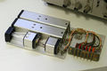
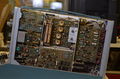
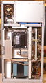
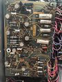
==Construction==
==Construction==
Revision as of 22:09, 1 March 2021
{{{manufacturer}}}
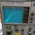
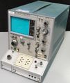
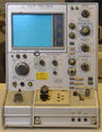
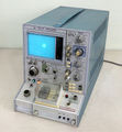
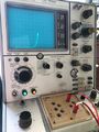
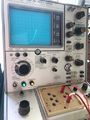
Curve tracer
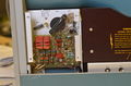
Tektronix 576 Curve tracer with 390-0098-00 standard test fixture
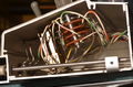
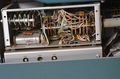
Except for the cathode ray tube (CRT), the 576 is all-solid-state.
It came out during the last four production years of the Type 575,
which used the then-current 500-series technology of ceramic strips for circuit tie points.
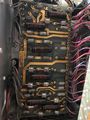
The 576 used updated construction much in the same style as that of
the 453 and 454 portable oscilloscopes, using printed circuit boards.
In fact, the 576 and 453 began life at about the same time.
The only reason the Type 575 remained in production was because the 176 pulsed high-current fixture
had not yet been developed for the 576,
and the Type 575 coupled with its Type 175 pulsed high-current fixture filled requirement for power semiconductors.
An interesting side note is that the 453 was introduced the same year as the 576;
the 453A and 454A were introduced at the same time as the 176 pulsed high-current adaptor for the 576.
The 576 is unequaled in performance and durability.
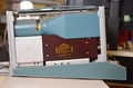
In physical volume, it is smaller than the Type 575, mostly due to a cabinet that slopes downward toward the back.
Its sloping front panel and sloping “front porch” where the various adaptors are installed make it much a more comfortable instrument to use.
In addition, the 576 sports an internal graticule and a larger display area.
Because of the power it is able to deliver to solid-state power semiconductors under test,
it is a surprisingly heavy instrument for its smaller size, and despite its solid-state design,
weighs in at 70-1/2 pounds vs. the 66-1/4 pound weight of the Type 575.
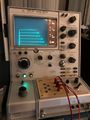
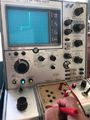
The display is large at 10 × 10 cm with an internal, parallax-free graticule.
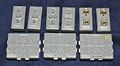
Along the right side of the CRT is an alphanumeric readout which puts the important front panel settings
where they can be photographed along with the displayed semiconductor curve.
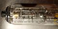
This display is a complex unit of fiber optic light-guides driven by incandescent lamps to provide alphabetic, numeric and Greek characters.
Given the front panel settings, the display automatically calculates beta/DIV.
The same readout modules were used in the short-lived 5030/5031 scope series.
The 576 was designed before the 7000-series scopes, and by a different engineering group,
or they might have shared information and technology to provide all of this
as on-screen readout like the 7000-series, and for less money than the technology they used.
Surprisingly, this fiber-optic unit has not proved to be the least bit troublesome,
considering all of the incandescent lamps required to implement the design.
Wise operators will keep the display illumination at a lower level to prolong lamp life.
Display positioning in both the horizontal and vertical dimensions is via a switch
which moves the beam a calibrated number of divisions and a potentiometer for fine control.
The little brother tracer, the 577, introduced at a later date, does not have this feature.
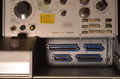
Test Fixtures
The interface connections to the teste fixtures are made through the same style of blue robust Amphenol 26-xxx-xx connectors as used with the plug-ins on the 500-series oscilloscope line.
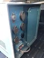
The collector voltage can be swept from zero to 1500 V in four ranges.
For the 75 V and higher ranges a plastic safety cover box must be installed in the test fixture and closed, otherwise a yellow warning light indicates that the collector voltage is disabled.
Because so many used 576s do not come with safety covers, some users defeat the safety interlock mechanically or electrically, which is hazardous given the lethal voltages and currents the 576 is capable of producing.
The instrument has uses other than displaying semiconductor curves.
The vertical system can be adjusted for high current sensitivities in the nanoamp region and with the availability of
1500 volts and DC operation vs. collector supply sweeping, can provide measurement of capacitor leakage currents that few other instruments can achieve.
This is handy for checking ceramic high voltage filter capacitors in defective supplies.
The 576 is capable of displaying curves for bipolar transistors, field-effect transistors, silicon-controlled rectifiers,
triacs, diacs, diodes and rectifiers, zener diodes, tunnel diodes … nearly any semiconductor imaginable.
If one constructs simple adaptors, the 576 can be used to check optocouplers and transistor arrays as well.
It is capable of pouring 20 amperes through a device up to a power level of 220 watts.
The demise of the original 575 came in 1971 when the 575's companion 175 pulsed high-current unit was no longer sold,
replaced by the 576 with its new 176 pulsed high-current adaptor.
The 575 itself disappeared from the catalog about a year later.
When production ended with its final appearance in the 1990 catalog,
the sales price of the 576 had escalated to a stunning $18,040, replaced by the 370 and 371 models selling for just a little bit more.
The 576 now sells on the eBay on-line auction site for anywhere from about $300 to over $2000,
usually offered without the safety shield or any adaptors and often without the standard test fixture which sellers seem to enjoy offering separately.
Many are sold with only the 176 pulsed high-current adaptor installed.
The small transistor adaptors are selling for nearly their original catalog price.
On average, the 576 is being sold on the used market for about 1/12 its last catalog price – or at about half the price when it first appeared in 1969.
Overall, the instrument has held its value and popularity very well.
Vacuum tubes can have their curves traced on a 576.
This requires a fixture that provides the heater current to the tube under test.
Pairs of tubes can be matched this way.
Alternatively, the two triodes in a dual-triode can be compared.
The Tektronix 570 (last sold around 1966) specializes in tube measurements
and has a built-in heater supply for the tube under test, which makes the 570 convenient.
However, with a custom fixture, the 576 can make most, if not all,
of the same measurements that can be made on a 570.
The AC collector sweep mode is useful when one wants a single plot showing the behavior of a device with positive and negative
voltages. For example, a zener diode typically starts conducting at a few hundred millivolts in the positive direction,
but has minimal reverse conduction until the zener voltage is reached, e.g., at 6.2 volts.
On a different subject, it might be noted here that the introduction of the 576 marked the approximate time
that Tektronix began moving from using the word “Type” in front of its model numbers (e.g., Type 545B) to simply using the model number only.