5CT1N: Difference between revisions
Jump to navigation
Jump to search
(Created page with "Curve Tracer Plug-in for the 5000 series oscilloscopes.") |
No edit summary |
||
| (25 intermediate revisions by 3 users not shown) | |||
| Line 1: | Line 1: | ||
Curve | {{Plugin Sidebar | ||
|manufacturer=Tektronix | |||
|series=5000-series scopes | |||
|type=5CT1N | |||
|summary=Curve tracer plug-in | |||
|image=5ct1n-crop.jpg | |||
|caption=5CT1N curve tracer | |||
|introduced=1972 | |||
|discontinued=1988 | |||
|designers=Matt Zimmerman | |||
|manuals= | |||
* [[Media:070-1246-00.pdf|Tektronix 5CT1N Manual]] | |||
* [[Media:062-1009-00.pdf|Semiconductor Device Measurements]] (''Concepts'' series) | |||
}} | |||
The '''Tektronix 5CT1N''' is a curve tracer plug-in for the 5000 series oscilloscopes, similar to the [[7CT1N]] for [[7000-series scopes]]. | |||
The 5CT1N was designed by [[Matt Zimmerman]]. | |||
{{BeginSpecs}} | |||
{{Spec | DUT drive voltage (C-E) | | |||
* positive (NPN or N channel) or negative (PNP or P channel) half-waves | |||
* 7.5 V, 0.5 V/Div, 240 mA peak | |||
* 30 V, 2 V/Div, 60 mA peak | |||
* 75 V, 5 V/Div, 24 mA peak | |||
* 300 V, 20 V/Div, 6 mA peak | |||
* HV warning light on for > 50 V | |||
* peak power 500 mW}} | |||
{{Spec | DUT current display | | |||
* 10 μA/Div to 20 mA/Div, 1−2−5 steps (x 1 mode) | |||
* 10 nA/Div to 20 μA/Div, 1−2−5 steps (x 1000 mode)}} | |||
{{Spec | Base/Gate drive | | |||
* 0 to at least 10 steps | |||
* dual polarity | |||
* variable offset, at least +/− 5 steps | |||
* current mode: 1 μA/Step to 1 mA/Step in 1−2−5 sequence | |||
* voltage mode: 1 mV/Div to 1 V/Div in 1−2−5 sequence, 1 kΩ current limit | |||
}} | |||
{{Spec | DUT connection | Three 4 mm jacks / binding posts}} | |||
{{Spec | DUT adapters | | |||
* [[013-0072-00]] Axial diodes | |||
* [[013-0069-00]] Devices with long leads | |||
* [[013-0070-01]] Transistors in TO-3 or TO-66 cases | |||
* [[013-0074-00]] Transistors with stud leads | |||
* [[013-0110-00]] Diodes with stud leads | |||
* [[013-0112-00]] Transistors in TO-36 cases | |||
* [[013-0128-00]] Transistors in TO-5 or TO-18 | |||
}} | |||
{{EndSpecs}} | |||
==Links== | |||
* [[Matt Zimmerman]], ''Oscilloscope to Curve Tracer with one Plug-in.'' [[Media:Tekscope_1972_V4_N6_Nov_1972.pdf|Tekscope Vol. 4 No. 6, Nov 1972]], p.7 | |||
* [http://www.ke5fx.com/A_VTCT_Adapter_for_All_Tektronix_SCTs_W7PF.pdf Dennis Tillman: An Inexpensive Vacuum Tube Curve Tracer Adapter for All Tektronix Semiconductor Curve Tracers] | |||
==Pictures== | |||
<gallery> | |||
5440.jpg | 5CT1N in [[5440]] mainframe vertical bay, X output connected to time base X input | |||
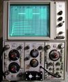
Tek-5ct1_in_use.jpg| Displaying transistor curves | |||
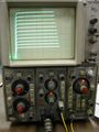
Tek 5ct1n f1.JPG | |||
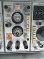
Tek 5ct1n front2.jpg | |||
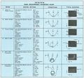
5CT1N 7CT1N Basic Measurement Reference Chart.jpg | |||
</gallery> | |||
==Common Problems== | |||
C30 and C32 (100 μF, 25 V) [http://hakanh.com/dl/docs/hardtofind/CT1N.pdf are under-rated] and therefore have a tendency to leak or short, | |||
causing associated resistors R30 and R32 (240 Ω, 0.25 W, 5%) to overheat and fail. | |||
C30 and C32 should be replaced with modern equivalents rated above 35 V. | |||
[[Category:Curve tracers]] | |||
[[Category:5000 series plugins]] | |||
Revision as of 04:57, 17 September 2022

The Tektronix 5CT1N is a curve tracer plug-in for the 5000 series oscilloscopes, similar to the 7CT1N for 7000-series scopes. The 5CT1N was designed by Matt Zimmerman.
Key Specifications
| DUT drive voltage (C-E) |
|
|---|---|
| DUT current display |
|
| Base/Gate drive |
|
| DUT connection | Three 4 mm jacks / binding posts |
| DUT adapters |
|
Links
- Matt Zimmerman, Oscilloscope to Curve Tracer with one Plug-in. Tekscope Vol. 4 No. 6, Nov 1972, p.7
- Dennis Tillman: An Inexpensive Vacuum Tube Curve Tracer Adapter for All Tektronix Semiconductor Curve Tracers
Pictures
-
5CT1N in 5440 mainframe vertical bay, X output connected to time base X input
-
Displaying transistor curves
-

-
-


Common Problems
C30 and C32 (100 μF, 25 V) are under-rated and therefore have a tendency to leak or short, causing associated resistors R30 and R32 (240 Ω, 0.25 W, 5%) to overheat and fail. C30 and C32 should be replaced with modern equivalents rated above 35 V.