7A16P: Difference between revisions
(Added two pictures) |
(correct links) |
||
| Line 96: | Line 96: | ||
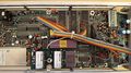
7A16P_with_cables.jpg | 7A16P right internal modified with cables for connection to [[021-0374-00]]. | 7A16P_with_cables.jpg | 7A16P right internal modified with cables for connection to [[021-0374-00]]. | ||
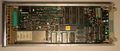
7A16P_with_cables_detail.jpg | 7A16P right internal modified for [[021-0374-00]], detail. | 7A16P_with_cables_detail.jpg | 7A16P right internal modified for [[021-0374-00]], detail. | ||
Tek_7A16P_late.jpg|A late version of the 7A16P with connectors for the [021-0374-00]] GPIB decoder | Tek_7A16P_late.jpg|A late version of the 7A16P with connectors for the [[021-0374-00]] GPIB decoder | ||
Tek_7A16P_decoder_conn.jpeg|Connectors for the [021-0374-00]]GPIB decoder on a late 7A16P | Tek_7A16P_decoder_conn.jpeg|Connectors for the [[021-0374-00]] GPIB decoder on a late 7A16P | ||
</gallery> | </gallery> | ||
Revision as of 11:05, 4 October 2020
The Tektronix 7A16P is a single-channel programmable vertical amplifier for 7000-series digitizing mainframes. All functions of the 7A16P can be remotely programmed via the GPIB 7000-series main interface bus, with exception of the variable gain control and the probe identify switch.
The 7A16P is special among the 7000-series vertical amplifiers in that it offers a switchable 1 MΩ/50 Ω input impedance, a feature otherwise only found in the 7A42. The 7A16P is also unique as it has two input BNC connectors, but is strictly a single channel plugin, having a switch that routes one of the BNC connectors to the amplifier circuits. This feature is handy in remote-controlled digitizing applications.
The plug-in was mainly intended for use in the 7612D and the 7912 family, but can also be used in the 7854 if paired with a 021-0374-00 GPIB interface and internally modified by adding cables for an 18-pin header and setting jumpers correctly. It is not recommended to use the 7A16P in any conventional 7000-series mainframe since it expects +5.1 V at pins B27 and A9 of the mainframe interface, and shorts them together. A9 is the 5 V light pin on conventional mainframes, and its current rating might be too low for successful operation of the 7A16P.
Key Specifications
| Bandwidth 1 | DC – 150 MHz at 1 MΩ, 250 MHz at 50 Ω |
|---|---|
| Deflection | 10 mV/Div to 5 V/Div in 1–2–5 sequence |
| Input impedance | 1 MΩ // 15 pF or 50 Ω |
| Features |
|
Internals
The input stage of the 7A16P contains miniature relays that switch between the two available input connectors, and select AC or DC coupling modes. Another relay is used to connect a 50 Ω shunt if the corresponding input impedance is selected. Further relays then select an optional 10x attenuator before the signal enters the input buffer, which contains an AC-coupled MOSFET common-drain amplifier and a DC-coupled operational amplifier configured in a feed-beside scheme. Gain switching is accommodated by several junction FETs that can insert another 10x attenuator in front of the MOSFET buffer, and 2× / 5× low-impedance attenuators after the input buffer.
The digital circuitry is built around a Motorola 6800 processor with several MC6821 Peripheral Interface Adapters that drive the switches of the analog circuit, and interface with the modified 7000-series internal GPIB bus.
Operation with 021-0374-00
When operated with the 021-0374-00, the 7A16P's modified GPIB bus is directly connected to it through an 18-pin, dual-row pin header and 17 leads. Following the labeling from the 021-0374-00 manual, the cable is connected as follows:
Pin Color Connected to Function 1 U1200 pin 10 I/O 0 2 U1200 pin 11 I/O 1 3 U1200 pin 12 I/O 2 4 U1200 pin 13 I/O 3 5 U1200 pin 14 I/O 4 6 U1200 pin 15 I/O 5 7 U1200 pin 16 I/O 6 8 U1200 pin 17 I/O 7 9 U500 pin 5 ATN 10 U1620 pin 6 NDAC 11 U1620 pin 8 NRFD 12 U1520 pin 9 DAV 13 U1620 pin 11 EOI 14 U1330 pin 13 IFC 15 U1200 pin 7 REN 16 U1620 pin 3 SND 17 U720 pin 8 SRQ
Additionally, jumper P1622 in the 7A16P should be set according to the 021-0374-00 manual. This connects the regular +5 V supply on A1 to the lights pin A9. In a 7854 mainframe, this will cause no direct harm if the rear "Control Illumination" switch is not in the "high" position since the 7854 uses series diodes to drop the light voltage if set to medium. However, the full lights current for all plugins will run through the 7A16P, so setting the switch to "high" is recommended.
Links
Pictures
-

7A16P front panel
-
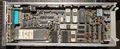
7A16P left internal
-
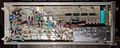
7A16P right internal
-

7A16P right internal modified with cables for connection to 021-0374-00.
-
7A16P right internal modified for 021-0374-00, detail.
-
A late version of the 7A16P with connectors for the 021-0374-00 GPIB decoder
-

Connectors for the 021-0374-00 GPIB decoder on a late 7A16P


Firmware (uploaded BIN files)
- 160-1511-00.bin (U30630 and U31630 in 7A16P)
- 160-1512-00.bin (U30830 and U31830 in 7A16P)