7L18: Difference between revisions
(cat) |
(template change) |
||
| Line 1: | Line 1: | ||
{{Plugin Sidebar| | {{Plugin Sidebar 2 | | ||
title=Tektronix 7L18| | title=Tektronix 7L18| | ||
summary=18 (60) GHz Spectrum Analyzer| | summary=18 (60) GHz Spectrum Analyzer| | ||
image=7L18-front.jpg| | image=7L18-front.jpg| | ||
caption=Tektronix 7L18| | caption=Tektronix 7L18| | ||
introduced=1978 | | |||
discontinued=(?) | | |||
series=[[7000-series scopes]]| | series=[[7000-series scopes]]| | ||
manuals= | manuals= | ||
| Line 29: | Line 29: | ||
The output of the sampler goes to the LO input on the mixer. The mixer IF output | The output of the sampler goes to the LO input on the mixer. The mixer IF output | ||
is 510 MHz. | is 510 MHz. | ||
==Specifications== | |||
''please add'' | |||
==Pictures== | ==Pictures== | ||
Revision as of 03:18, 23 August 2014
Template:Plugin Sidebar 2 The Tektronix 7L18 is a spectrum analyzer plug-in introduced in 1978 for 7000-series scopes. It occupies three plug-in bays in the oscilloscope.
The 7L18 covers the range from 1.5 GHz to 18 GHz with the internal mixer and 12.5 GHz to 60 GHz using external mixers. Note that it will NOT do 1.5 GHz to 18 GHz in one span, it will only max span the range selected by the BAND/HARMONIC control. This range is determined by the heterodyne harmonic number and sign (sideband) and the range of the first LO, which is 2 GHz to 4 GHz.
The input attenuator range is 0 dB to 60 dB in 10 dB steps and is a standard Weinschel Engineering product driven by a belt. The range is encoded for the digital dBm reference level display. The signal then passes through a YIG preselector filter with a 50 MHz bandwidth. After the YIG filter, the signal enters the RF input of the mixer assembly.
The LO is a YIG tuned oscillator covering the 2 GHz to 4 GHz range. Its output passes through a sampler assembly used to PLL the YIG on small resolution bandwidths. The output of the sampler goes to the LO input on the mixer. The mixer IF output is 510 MHz.
Specifications
please add
Pictures
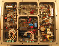
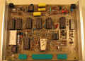
Service views:
-
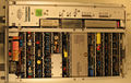
Top view
-
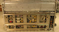
Bottom view
-
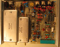
Service setup for the right front panel


Boards within the digital card cage (from back to front):
-
CRT Readout board
-
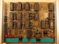
Center Freq Readout board
-
Sweep Horiz board
-
Span Atten board
-
Phase Lock module, rear
-
Phase Lock module, front
-
Phase Lock Logic CTL
-
VR Noise Filter
-
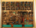
Log & Video Amp
-
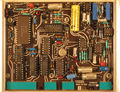
Center Freq DVM
-
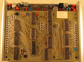
Digital Storage, front
-
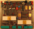
Digital Storage, back
-
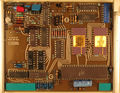
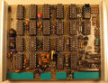
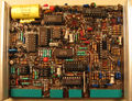
Micro Computer


The microcomputer board is built using three very old Intel chips: an Intel 4004 processor, an Intel 4002 320-bit RAM and 4-bit output port, and an Intel D4289 standard memory interface. The D4289 connects the 4004 to the two 2K8 ROMs. Note that in an earlier version of the 7L18 there were 6 ROMs.
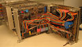
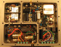
Internal views of the analog parts:
-
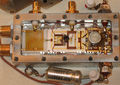
Internal of the LO sampler
