B170-V: Difference between revisions
Jump to navigation
Jump to search
(Created page with "The B170-V is a an attenuator for the 517. <gallery> File:Tek b170-v top.jpg File:Tek b170-v inside.jpg File:Tek b170-v trimmed.jpg|Hand-trimmer resistors </gallery>") |
No edit summary |
||
| (10 intermediate revisions by 3 users not shown) | |||
| Line 1: | Line 1: | ||
The B170-V is a | {{Instrument Sidebar | ||
|manufacturer=Tektronix | |||
|model=B170-V | |||
|class=Attenuator | |||
|series= | |||
|summary=70 Ω attenuator for the [[517]] | |||
|image=Tek b170-v top.jpg | |||
|caption=Tektronix B170-V | |||
|introduced=(?) | |||
|discontinued=(?) | |||
|designers= | |||
|manuals= | |||
* ''please add'' | |||
}} | |||
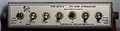
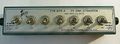
The '''B170-V''' is a 170 Ω attenuator for the [[517]]. Switches select from 0 to 64 dB of attenuation. | |||
[[John Addis]] wrote: | |||
<blockquote> | |||
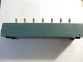
The inductors compensate for the switch stray capacitances. | |||
When the Ls and the stray Cs are connected like that, they constitute a lumped element delay line. | |||
The intent is not to make a delay line, but compensate out all the stray Cs by making a lumped delay line out of it. | |||
That extends the bandwidth and makes the impedance 170 ohms (up to 1 GHz or so) rather than a bunch of Cs sitting on the connection from input to output. | |||
</blockquote> | |||
==Pictures== | |||
<gallery> | <gallery> | ||
Tek b170-v top.jpg | |||
B170-V_1.jpg | A (?) | |||
B170-A_2.jpg | |||
B170-A_3.jpg | |||
Tek b170-v inside.jpg | |||
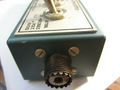
Tek b170-v trimmed.jpg|Hand-trimmed resistors | |||
Tek 517a b170a att.png|Schematic | |||
</gallery> | </gallery> | ||
[[Category:Attenuators]] | |||
Revision as of 12:21, 18 August 2021

The B170-V is a 170 Ω attenuator for the 517. Switches select from 0 to 64 dB of attenuation.
John Addis wrote:
The inductors compensate for the switch stray capacitances. When the Ls and the stray Cs are connected like that, they constitute a lumped element delay line. The intent is not to make a delay line, but compensate out all the stray Cs by making a lumped delay line out of it. That extends the bandwidth and makes the impedance 170 ohms (up to 1 GHz or so) rather than a bunch of Cs sitting on the connection from input to output.
Pictures
-
-
A (?)
-
-
-

-
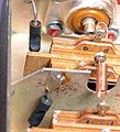
Hand-trimmed resistors
-
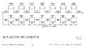
Schematic


