Nelson-Ross PSA-011: Difference between revisions
No edit summary |
No edit summary |
||
| Line 14: | Line 14: | ||
The voltage-controlled local oscillator is tuned | The voltage-controlled local oscillator is tuned | ||
using a variable-reactance tube, V6, a [[6201]]. | using a variable-reactance tube, V6, a [[6201]]. | ||
There were at least two major versions produced, without changing the model number. Compare the picture from the manual below with the other front panel photographs. | |||
There was also a tracking generator, called the Nelson Ross 101 SYNCHRO-SWEEP Generator. These are very rare. | |||
* [http://w140.com/kurt/nelson_ross_001-002-003-011-012-013.pdf Manual for Nelson-Ross 001, 002, 003, 011, 012, and 013 (PDF)] | * [http://w140.com/kurt/nelson_ross_001-002-003-011-012-013.pdf Manual for Nelson-Ross 001, 002, 003, 011, 012, and 013 (PDF)] | ||
<gallery> | <gallery> | ||
File:PC280162.JPG| | File:NR-011-manual-image.png|Front panel, as shown in manual. | ||
File:PC280163.JPG| | File:PC280162.JPG|Front | ||
File:PC280172.JPG| | File:PC280163.JPG|Front 2 | ||
File:PC280171.JPG| | File:PC280172.JPG|Front right | ||
File:PC280170.JPG| | File:PC280171.JPG|Front left | ||
File:PC280165.JPG| | File:PC280170.JPG|Bottom | ||
File:PC280166.JPG| | File:PC280165.JPG|Bottom 2 | ||
File:PC280173.JPG| | File:PC280166.JPG|Left | ||
File:PC280174.jpg| | File:PC280173.JPG|Rear right | ||
File:PC280169.JPG| | File:PC280174.jpg|Rear | ||
File:PC280164.JPG| | File:PC280169.JPG|Rear 2 | ||
Nelson-ross_011_schem_sm.png| | File:PC280164.JPG|Rear 3 | ||
Nelson-ross_011_schem_sm.png|Schematic | |||
</gallery> | </gallery> | ||
Revision as of 13:02, 19 April 2014
The Nelson-Ross PSA-011 is a spectrum analyzer plug-in for 500-series scopes. The center frequency range is 10 Hz to 20 kHz. It can display amplitude in linear or log scale.
The input is high-impedance and is AC-coupled. The PSA-011 is a single-conversion architecture with a pair of 6BH6 tubes serving as a balanced mixer. After IF filtering and amplification, the signal is detected using a 1N34A germanium diode. The detected voltage from the diode directly drives pin 3 (vertical -) of the scope plug-in interface connector. Pin 1 (vertical +) of the scope plug-in interface connector is fed a DC vertical position voltage by the PSA-011.
The voltage-controlled local oscillator is tuned using a variable-reactance tube, V6, a 6201.
There were at least two major versions produced, without changing the model number. Compare the picture from the manual below with the other front panel photographs.
There was also a tracking generator, called the Nelson Ross 101 SYNCHRO-SWEEP Generator. These are very rare.
-
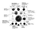
Front panel, as shown in manual.
-
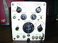
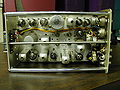
Front
-

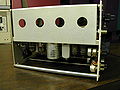
Front 2
-

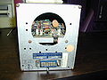
Front right
-
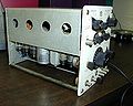
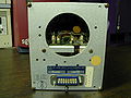
Front left
-
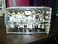
Bottom
-
Bottom 2
-
Left
-

Rear right
-

Rear
-
Rear 2
-
Rear 3
-
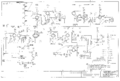
Schematic


