RSA-DKIT: Difference between revisions
Jump to navigation
Jump to search
No edit summary |
No edit summary |
||
| (One intermediate revision by the same user not shown) | |||
| Line 1: | Line 1: | ||
{{ | {{Instrument Sidebar | ||
|class=Spectrum Analyzer | |||
summary=USB Demo Kit for Spectrum Analyzers | | |manufacturer=Tektronix | ||
image= RSA-DKIT_1.jpg | | |model=RSA-DKIT | ||
caption=Tektronix RSA-DKIT | | |summary=USB Demo Kit for Spectrum Analyzers | ||
introduced=(?) | | |image= RSA-DKIT_1.jpg | ||
discontinued=(?) | | |caption=Tektronix RSA-DKIT | ||
manuals= | |introduced=(?) | ||
* [[Media: 37W-60476- | |discontinued=(?) | ||
* [[Media: 071-3330- | |manuals= | ||
* [[Media:37W-60476-0.pdf|RSA Demo Kit Datasheet]] | |||
* [[Media:071-3330-02.pdf|RSA DKIT Self-Guided Demo]] | |||
}} | }} | ||
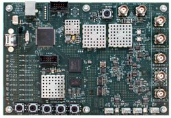
The '''RSA-DKIT''' is a demonstration kit for USB spectrum analyzers which produces 16 different signals to help users learn spectrum analysis and measurement methods. | The '''RSA-DKIT''' is a demonstration kit for USB spectrum analyzers which produces 16 different signals to help users learn spectrum analysis and measurement methods. | ||
Internal signals consist of: | Internal signals consist of: | ||
* Continuous 24415.312 MHz sine wave, | * Continuous 24415.312 MHz sine wave, –5 dBm | ||
* Infrequent hop -5 dBm CW signal centered around 2445.312 MHz which will hop to 2458.2 MHz every 1.28 seconds for approximately 155 µs | * Infrequent hop -5 dBm CW signal centered around 2445.312 MHz which will hop to 2458.2 MHz every 1.28 seconds for approximately 155 µs | ||
* CW pulse centered around 2445.312 GHz ON for 10 µs and OFF for 90 µs | * CW pulse centered around 2445.312 GHz ON for 10 µs and OFF for 90 µs | ||
| Line 33: | Line 34: | ||
* USB: Two USB 1.0/2.x ports for power, minimum 800 mA minimum | * USB: Two USB 1.0/2.x ports for power, minimum 800 mA minimum | ||
* External I and Q inputs: DC to 5 MHz, 50 Ω inputs, | * External I and Q inputs: DC to 5 MHz, 50 Ω inputs, 1 V<sub>p-p</sub> (+4 dBm) maximum | ||
* Baseband I and Q outputs: DC to 5 MHz, 50 Ω inputs, ±100 mV into 50 Ω | * Baseband I and Q outputs: DC to 5 MHz, 50 Ω inputs, ±100 mV into 50 Ω | ||
* RF output: 50 Ω [[BNC connector]] female | * RF output: 50 Ω [[BNC connector]] female | ||
Latest revision as of 02:27, 14 October 2022
The RSA-DKIT is a demonstration kit for USB spectrum analyzers which produces 16 different signals to help users learn spectrum analysis and measurement methods.
Internal signals consist of:
- Continuous 24415.312 MHz sine wave, –5 dBm
- Infrequent hop -5 dBm CW signal centered around 2445.312 MHz which will hop to 2458.2 MHz every 1.28 seconds for approximately 155 µs
- CW pulse centered around 2445.312 GHz ON for 10 µs and OFF for 90 µs
- Linear FM pulse with a carrier at 2445.312 MHz and a linear chirp in a 10 MHz sweep
- Pulse train consisting of two 100-pulse patterns separated by 5 ms and repeated once every second
- QPSK 1 carrier at 2445.312 GHz with a symbol rate of 3.072 MS/sec and a PRBS9 pattern
- QPSK 2 carrier at 2445.312 GHz with a symbol rate of 3.84 MS/sec and a PRBS11 pattern
- OFDM (801.11p) standard 100 MHz wide packet that repeats every 2 ms
- AM carrier at 2445.312 MHz at a modulation rate of 1.00 kHz
- FM carrier at 2445.312 MHz at a modulation rate of 1.00 kHz
- SPECMON continuous 10 MHz LFM pulse superimposed with a FM signal -40 dB down
- Spur search consisting of a two-tone waveform with tones at +1 MHz and +4 MHz relative to the center frequency of 2445.312 MHz
- Waveform 15 (P25 C4FM) is a P25 standard continuous C4FM signal with a bandwidth of 12.5 kHz
- Waveform 16 (P25 HCPM) is a P25 standard continuous HCPM (Inbound) signal with a bandwidth of 12.5 kHz
Inputs and outputs consist of:
- USB: Two USB 1.0/2.x ports for power, minimum 800 mA minimum
- External I and Q inputs: DC to 5 MHz, 50 Ω inputs, 1 Vp-p (+4 dBm) maximum
- Baseband I and Q outputs: DC to 5 MHz, 50 Ω inputs, ±100 mV into 50 Ω
- RF output: 50 Ω BNC connector female
- Noise source bias input: 0 V (disable) or +28 V (enable), 17 mA nominal
- Noise Out: Produces -20 dB excess noise from 10 MHz to 3 GHz when powered by an external +28 V
Included Accessories are N (male) to BNC (female) adapter, whip antenna, and printed demo guide


