SC504: Difference between revisions
m (→top: clean up, replaced: manuals= → designers= |manuals=) |
No edit summary |
||
| Line 1: | Line 1: | ||
{{TM500 | mfg=Tektronix | type=SC504 | function=80 MHz dual-channel oscilloscope | class=oscilloscope | image=Tek_sc504_3.jpg | introduced=1978 | discontinued=1993 | | {{TM500 | mfg=Tektronix | type=SC504 | function=80 MHz dual-channel oscilloscope | class=oscilloscope | image=Tek_sc504_3.jpg | introduced=1978 | discontinued=1993 | | ||
designers= |manuals= | designers= |manuals= | ||
* [ | * [[Media:070-2296-00.pdf|Tektronix SC504 Manual]] (PDF) | ||
* [[Media:TB-9-6625-2173-35.pdf|US Army Calbration Guide for SC501, SC502, and SC504 (PDF)]] | * [[Media:TB-9-6625-2173-35.pdf|US Army Calbration Guide for SC501, SC502, and SC504 (PDF)]] | ||
* [[Media:TM-9-6695-246-34P.pdf|TM-9-6695-246-34P Parts List]] | * [[Media:TM-9-6695-246-34P.pdf|TM-9-6695-246-34P Parts List]] | ||
}} | }} | ||
{{BeginSpecs}} | {{BeginSpecs}} | ||
{{Spec | Bandwidth | 80 MHz (derated to 70 MHz from 35 °C to 50 °C ambient), 10 Hz AC coupling cutoff }} | {{Spec | Bandwidth | 80 MHz (derated to 70 MHz from 35 °C to 50 °C ambient), 10 Hz AC coupling cutoff }} | ||
Revision as of 11:09, 15 August 2021

The Tektronix SC504 is a 80 MHz dual-channel oscilloscope plug-in for the TM500 system.
Key Specifications
| Bandwidth | 80 MHz (derated to 70 MHz from 35 °C to 50 °C ambient), 10 Hz AC coupling cutoff |
|---|---|
| Rise time | 4.4 ns (derated to 5.0 ns from 35 °C to 50 °C ambient) |
| Deflection | 5 mV/Div to 10 V/Div, 1−2−5, and ×2.5 variable; max. input 250 V (DC coupled), 400 V (AC) |
| Sweep | 50 ns/Div to 200 ms/Div, 1−2−5; variable ×2.5 (to at least 0.5 s/Div); ×10 magnifier |
| Trigger | 0.4 div or 60 mV, DC to 30 MHz; 1.5 div or 150 mV, 30 MHz to 80 MHz; AC coupling >50 Hz; AC LF REJ >10 kHz; HF REJ <50 kHz |
| Input impedance | 1 MΩ // 20 pF |
| Ext Trig Input | 1 MΩ // 24 pF (750 kΩ // 28 pF when not selected), max. 250 V DC+peak AC) |
| CRT | 8×10 divisions of 6.35 mm (0.25") each; 12 kV acceleration, P31 phoshor; 154-0730-05 tube |
| Calibrator | 0.6 Vp-p @ 1 kHz |
| Power | approx. 26 W operating, <1 W in standby |
| Features | 1-or 2-channel (chop/alt), Add (1+2), Subtract (1-2), X-Y mode (2 MHz, <3° to 50 kHz), single sweep |
Links
Rear interface
The SC504 has dedicated rear interface signal inputs switchable from the front panel AC/DC/GND/Int DC coupling selectors. These are terminated in 50 Ω (max. 5 VRMS, 0.5 W).
Additionally, it provides a trigger input, Z-axis input (±5 V), delayed gate input (ECL), gate select input (ground for ext gate), intensify input (ECL), Ch1 trigger output (>50 mV/Div, 30 MHz), triggered gate output (ECL), holdoff output (ECL), ramp output (0−10 V), sweep reset input, ready light output, and +5 V.
Internals
A slide switch under the right side cover allows the variable sweep control to be used as a variable holdoff control instead.
The SC504 uses some custom Tek ICs, namely the 155-0124-00 preamplifier (U4345), 155-0109-01 trigger (U3238), and 155-0122-00 A-B logic (U3158). There are two passive input attenuator hybrids (HY1520, HY1420) and two 155-0161-00 attenuator/amplifier hybrids (HY1530, HY1430).
The power supply uses the pass transistors provided by the two mainframe slots that the SC504 covers. Those on the right slot provide ±20 V from the mainframe's ±33.5 V rails, those on the left slot make +5 V from the +11.5 V rail and −5 V from the rectified 17 VAC supply. Power is drawn from the right mainframe slot, the pass transistors are the only connections on the left slot.
Pictures
-
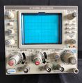
front panel
-
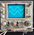
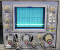
in operation (2ch)
-
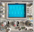
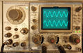
in operation
-
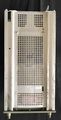
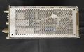
top
-
right
-
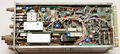
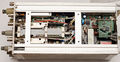
right interior
-

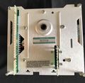
left
-
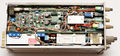
left interior
-
bottom
-
bottom interior
-
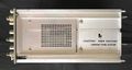
rear
-
in operation
-

SC504 with non-Tek plug-ins
-
SC504 with FG501
-


