Uploads by Maurizio
Jump to navigation
Jump to search
This special page shows all uploaded files.
| Date | Name | Thumbnail | Size | Description | Versions |
|---|---|---|---|---|---|
| 17:47, 3 October 2020 | Tektronix561 NO040347FieldModification.pdf (file) |  |
69.93 MB | 1 | |
| 17:45, 3 October 2020 | Tektronix561 NO040288FieldModification.pdf (file) |  |
42.26 MB | 1 | |
| 17:43, 3 October 2020 | Tektronix561 NO040267FieldModification.pdf (file) |  |
12.82 MB | 1 | |
| 17:40, 3 October 2020 | 070-261.pdf (file) |  |
246.79 MB | Full service manual including field modification instructions. | 1 |
| 12:06, 17 July 2019 | 5A21N TopClose1.jpg (file) |  |
5.59 MB | Rear, left side. | 1 |
| 12:05, 17 July 2019 | 5A21N Top.jpeg (file) |  |
2.44 MB | Left side. | 1 |
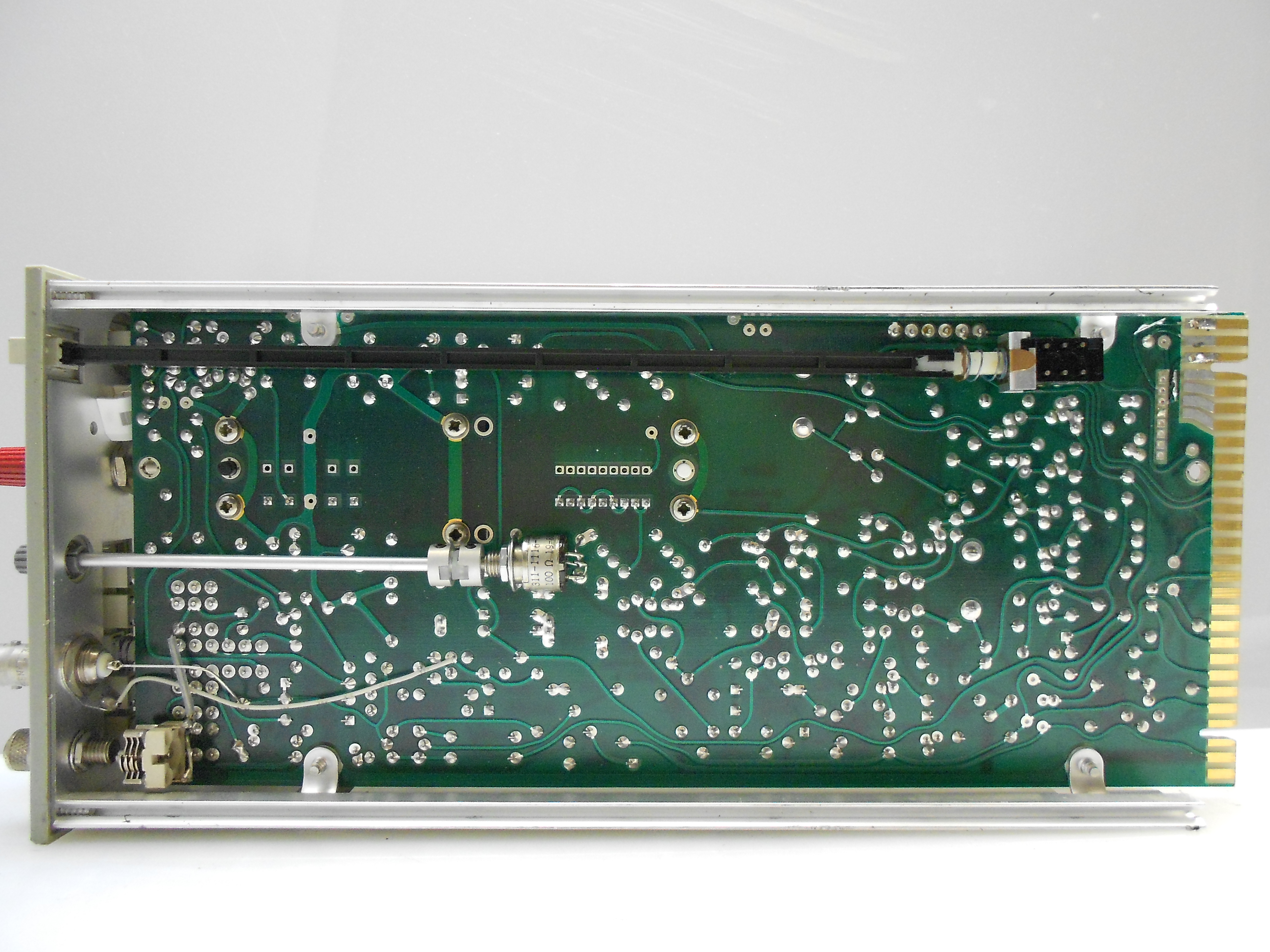
| 12:04, 17 July 2019 | 5A21N Bot.jpg (file) |  |
5.72 MB | Right side. | 1 |
| 12:04, 17 July 2019 | 5A21N BotClose.jpg (file) |  |
5.67 MB | Bottom side, front of plugin. | 1 |
| 12:03, 17 July 2019 | 5A21N TopClose2.jpg (file) |  |
5.72 MB | Inputs and input protection. | 1 |
| 12:01, 17 July 2019 | 5A21N Front.jpeg (file) |  |
1.35 MB | Front Panel of 5A21N with clear knob skirt. | 1 |
| 09:40, 17 July 2019 | Type67 Top.jpg (file) |  |
5.72 MB | Top side of the Type 67. | 1 |
| 09:37, 17 July 2019 | Type67 Bot.jpeg (file) |  |
2.54 MB | Component side of the Type 67. | 1 |
| 09:35, 17 July 2019 | Type67 Mod104Number.jpg (file) |  |
5.45 MB | Serial number and modification number. | 1 |
| 09:34, 17 July 2019 | Type67 Mod104 1.jpg (file) |  |
5.57 MB | Closeup of the modification. | 1 |
| 09:31, 17 July 2019 | Type67 Mod104 2.jpg (file) |  |
5.37 MB | Closeup of the modification. | 1 |
| 09:30, 17 July 2019 | Type67Mod104 Front.jpeg (file) |  |
1.68 MB | A type 67 time base plugin with 'Mod 104'. | 1 |
| 09:28, 17 July 2019 | 561 Back.jpeg (file) |  |
2.08 MB | Back of the 561 indicator unit. Note the power transistor fo the low voltage supply. | 1 |
| 09:27, 17 July 2019 | 561 FrontControls.jpeg (file) |  |
2.11 MB | Front panel controls of the 561. | 1 |
| 09:25, 17 July 2019 | 561 HVCover.jpg (file) |  |
5.6 MB | High voltage cover. | 1 |
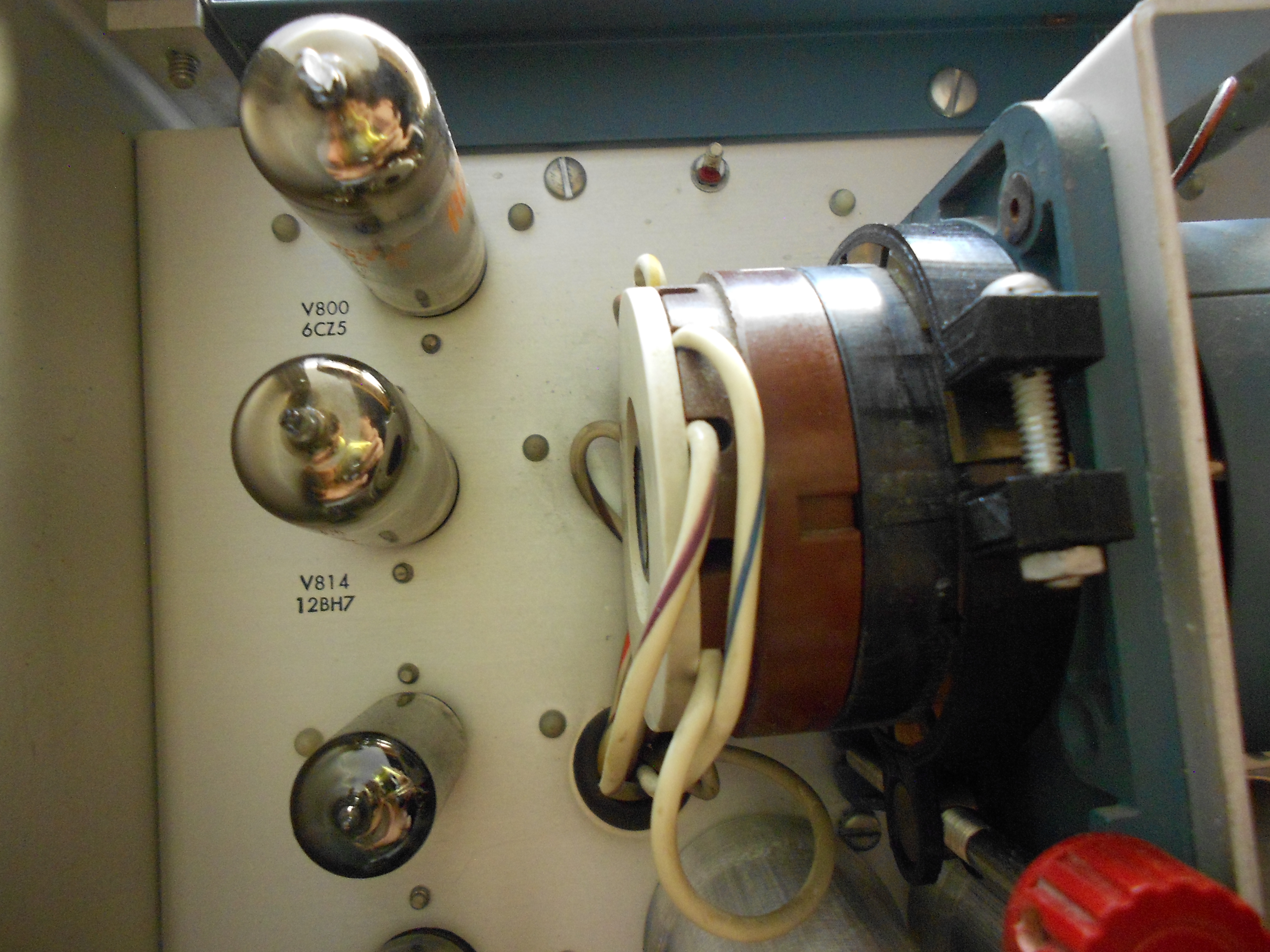
| 09:24, 17 July 2019 | 561 LeftClose.jpg (file) |  |
5.63 MB | Power supply tubes and filter capacitors. | 1 |
| 09:22, 17 July 2019 | 561 CRTSocket.jpg (file) |  |
5.52 MB | Closeup of the CRT socket. | 1 |
| 09:21, 17 July 2019 | 561 BayConnector.jpg (file) |  |
5.69 MB | Closeup of the back of the plugin connector in the right bay. | 1 |
| 09:20, 17 July 2019 | 561 CRTNeck.jpg (file) |  |
5.54 MB | Deflection plate connections. | 1 |
| 09:17, 17 July 2019 | 561 Calibrator.jpg (file) |  |
5.62 MB | Calibration signal generator for the front panel calibrator. | 1 |
| 09:15, 17 July 2019 | 561 PSU HV.jpg (file) |  |
5.67 MB | CRT high voltage power supply. The 561 has a cathode voltage of -3.3 kV. | 1 |
| 09:12, 17 July 2019 | 561 PSU LV.jpg (file) |  |
5.7 MB | Low voltage regulator. Pass transistor is mounted on the back of the unit. | 1 |
| 09:11, 17 July 2019 | 561 PSU.jpg (file) |  |
5.66 MB | Closeup of the regulator circuits. | 1 |
| 09:09, 17 July 2019 | 561 Right.jpeg (file) |  |
2.61 MB | Right side of the 561 indicator unit. | 1 |
| 09:07, 17 July 2019 | 561 Left.jpeg (file) |  |
2.55 MB | Left side of the 561 indicator unit. | 1 |
| 19:56, 16 July 2019 | 561 Front.jpeg (file) |  |
1.89 MB | Early 561 with round CRT and external graticule. | 1 |