Tunnel diodes: Difference between revisions
No edit summary |
No edit summary |
||
| (5 intermediate revisions by 2 users not shown) | |||
| Line 1: | Line 1: | ||
Tunnel diodes are used in various circuits in Tektronix gear made from the early | '''Tunnel diodes (Esaki diodes)''' are used in various circuits in Tektronix gear made from the early 1960s until the 1980s. | ||
== Applications == | == Applications == | ||
Tunnel diodes were used where it was | Tunnel diodes were used where it was desirable to have fast and clean switching between two states. | ||
desirable to have fast and clean switching between two states. | |||
They were used in | They were used in | ||
* trigger circuits as Schmitt triggers, | * trigger circuits as Schmitt triggers, | ||
| Line 14: | Line 13: | ||
== Relevant Distinguishing Parameters == | == Relevant Distinguishing Parameters == | ||
Many different types of tunnel diodes were made. The primary parameter that describes one is the peak current, which is the current at the top of the hill in the I-V curve. The other two relevant electrical parameters are the capacitance of the diode and whether it is made of GaAs or Ge. In some circuits, | Many different types of tunnel diodes were made. The primary parameter that describes one is the peak current, which is the current at the top of the hill in the I-V curve. The other two relevant electrical parameters are the capacitance of the diode and whether it is made of GaAs or Ge. In some circuits, another model of tunnel diode can be substituted with only minor modifications to the surrounding circuit. [[Stan Griffiths]] describes such a modification here: | ||
another model of tunnel diode can be substituted with only minor modifications to the surrounding circuit. [[Stan Griffiths]] describes such a modification here: | |||
* [[Tunnel Diode Replacement and Modification]] | * [[Tunnel Diode Replacement and Modification]] | ||
| Line 35: | Line 33: | ||
(Alternatively and equivalently, it can be modeled as nonlinear resistance. However, the nonlinear VCCS model might be preferable because it avoids | (Alternatively and equivalently, it can be modeled as nonlinear resistance. However, the nonlinear VCCS model might be preferable because it avoids | ||
the confusing notion of negative resistance.) | the confusing notion of negative resistance.) | ||
Consider a tunnel diode biased by a DC current source that is slowly brought up from zero to a current just a few microamperes less than the diode's peak current. | Consider a tunnel diode biased by a DC current source that is slowly brought up from zero to a current just a few microamperes less than the diode's peak current. | ||
The quiescent voltage will be just less than the peak voltage. | The quiescent voltage will be just less than the peak voltage. | ||
Note that the I-V curve is nearly horizontal at this point, and therefore the incremental resistance of the diode is very high at this point. | Note that the I-V curve is nearly horizontal at this point, and therefore the incremental resistance of the diode is very high at this point. | ||
For simplicity, we can assume that the incremental resistance is infinite at this quiescent point. | For simplicity, we can assume that the incremental resistance is infinite at this quiescent point. | ||
| Line 99: | Line 99: | ||
===Textbooks and references=== | ===Textbooks and references=== | ||
* Wikipedia: [[wikipedia:Tunnel diode|Tunnel Diode]] / [[wikipedia:Backward diode|Backward Diode]] | * Wikipedia: [[wikipedia:Tunnel diode|Tunnel Diode]] / [[wikipedia:Backward diode|Backward Diode]] | ||
* | * [[Media:Millman taub chapters 12 and 13.pdf|Millman and Taub Pulse, Digital and Switching Waveforms Chapters 12 and 13]] | ||
* | * [[Media:Gentile-TunnelDiodes.pdf|Sylvester P. Gentile: Basic Theory and Application of Tunnel Diodes (1962)]] | ||
* Tunnel diode switching circuits and the back diode. Service Scope [[Media:Service Scope 38 Jun 1966.pdf | No. 38, June 1966]] and [[Media:Service Scope 39 Aug 1966.pdf | No. 39, August 1966]] | * Tunnel diode switching circuits and the back diode. Service Scope [[Media:Service Scope 38 Jun 1966.pdf | No. 38, June 1966]] and [[Media:Service Scope 39 Aug 1966.pdf | No. 39, August 1966]] | ||
* [ | * [https://w140.com/GenRad_Experimenter_July-Aug_1960.pdf Article by General Radio on Tunnel Diode Measurements] | ||
* [ | * [https://www.tpub.com/neets/book7/26a.htm tpub.com: The Tunnel Diode] | ||
* [ | * [https://w140.com/aec-nasa_april69_tunnel_diodes.pdf AEC - NASA Tech Brief 69-10116 (1969): Simple Tunnel Diode Circuit for Accurate Zero Crossing Timing] | ||
* [ | * [https://w140.com/Nucl_Instrum_Methods_TD_Induct_effects_1968.pdf Nuclear Instruments and Methods 66 (1968): Inductance Effects on Capacitive Loading of a Tunnel Diode] | ||
* [ | * [https://w140.com/andrews_directional-coupler_td_trig.pdf Andrews "Directional-Coupler Technique for Triggering a Tunnel Diode"] | ||
* [ | * [https://w140.com/andrews_nahman_flat_pulse_gen.pdf Andrews and Nahman "Reference Waveform Flat Pulse Generator"] | ||
* [ | * [https://w140.com/andrews_improved_td_pulse_bias.pdf Andrews "Improved Bias Supply for Tunnel-Diode Picosecond Pulse Generators"] | ||
* [ | * [https://w140.com/nasa_paull_tunnel_diode_logic.pdf NASA Technical Note: Paull, Cancro, and Garrahan, "Low Power Nanosecond Pulse and Logic Circuits Using Tunnel Diodes"] | ||
* [[Media:Diode-Circuits-Handbook-Rufus-Turner.pdf|Rufus P. Turner, "Diode Circuits Handbook"]] | * [[Media:Diode-Circuits-Handbook-Rufus-Turner.pdf|Rufus P. Turner, "Diode Circuits Handbook"]] | ||
* [https://www.americanmicrosemi.com/tutorial/tunnel-diode-and-back-diode/ American Micro Semiconductor: Tunnel Diode and Back Diode] | * [https://web.archive.org/web/20211016024914/https://www.americanmicrosemi.com/tutorial/tunnel-diode-and-back-diode/ American Micro Semiconductor: Tunnel Diode and Back Diode] (archived webpage) | ||
* [[Media:L'Archeveque-RV-1965-PhD-Thesis.pdf]] | * [[Media:L'Archeveque-RV-1965-PhD-Thesis.pdf]] | ||
{{Documents|Link=Tunnel diodes}} | |||
===Cross-reference=== | ===Cross-reference=== | ||
* [ | * [[Media:Tektronix_Tunnel_Diodes_Cross_Reference.pdf|Tektronix diode cross reference - Tunnel, Back, Four-layer, Varicap, Snap-off, Suppressor, PIN]] | ||
* [ | * [https://w140.com/tunnel_diodes_table_cs.html Craig Sawyers' 1N tunnel diode summary table] | ||
* [[Russian tunnel diodes]] | * [[Russian tunnel diodes]] | ||
* See also [[:Category:Tunnel diodes]] / [[:Category:Back diodes]] | * See also [[:Category:Tunnel diodes]] / [[:Category:Back diodes]] | ||
===General Electric=== | ===General Electric=== | ||
* [ | * [https://w140.com/GE_Tunnel_Diode_Manual.pdf General Electric Tunnel Diode Manual, 1st ed. 1961] | ||
* [ | * [https://w140.com/Ge1961TunnelDiodeManual.pdf General Electric Tunnel Diode Manual (1961)] | ||
* General Electric Transistor Manual (1964) | * General Electric Transistor Manual (1964) | ||
** [ | ** [https://w140.com/ge_transistor_manual_1964-ch14_td.pdf Chapter 14: Tunnel Diode Circuits] | ||
** [ | ** [https://w140.com/ge_transistor_manual_1964-tunnel-diode_specs.pdf Chapter 19: Tunnel Diode Specifications] | ||
* [ | <!-- MISSING * [https://w140.com/kurt/ge_tunnel_diodes_71.pdf General Electric Tunnel Diode Specifications (1971)] --> | ||
* [ | * [https://w140.com/td262a.pdf GE TD26x/TD27x Datasheet] | ||
* [[Media:General Electric semiconductors 1966 HRFE.pdf|General Electric Tunnel Diodes in 1966 Transistor Catalog ( | * [[Media:General Electric semiconductors 1966 HRFE.pdf|General Electric Tunnel Diodes in 1966 Transistor Catalog]] (OCR) | ||
* [[Media:GE Research Information Services Tunnel Diodes.pdf|1959 General Electric Research Information Services Report on Tunnel Diodes | * [[Media:GE Research Information Services Tunnel Diodes.pdf|1959 General Electric Research Information Services Report on Tunnel Diodes]] | ||
* [[Media:Ge 1n3712-1n3721.pdf|General Electric 1N3712 to 1N3721 Data | * [[Media:Ge 1n3712-1n3721.pdf|General Electric 1N3712 to 1N3721 Data]] | ||
===RCA=== | ===RCA=== | ||
* [[Media:RCA 1963 Tunnel Diode Manual.pdf | RCA 1963 Tunnel Diode Manual ( | * [[Media:RCA 1963 Tunnel Diode Manual.pdf | RCA 1963 Tunnel Diode Manual]] (OCR) | ||
===Other Manufacturers=== | ===Other Manufacturers=== | ||
* [ | <!-- MISSING * [https://w140.com/kurt/gpd_tunnel_datasheet.pdf Germanium Power Devices Corp. Tunnel Diode Specifications, 6/1985] (1N3712–20, 1N3713–21) --> | ||
* [[Media:1n3271 to 1n4399b.pdf|1N3271 to 1N4399B Specs (PDF)]] | * [[Media:1n3271 to 1n4399b.pdf|1N3271 to 1N4399B Specs (PDF)]] | ||
* [[Media:Tunnel diodes in 1961 D.A.T.A. book.pdf|Tunnel Diodes Section of 1961 D.A.T.A. book]] (full book: https://archive.org/details/DATASemiconductorDiodeRectifierCharacteristicsTabulation1961VolVII) | * [[Media:Tunnel diodes in 1961 D.A.T.A. book.pdf|Tunnel Diodes Section of 1961 D.A.T.A. book]] (full book: https://archive.org/details/DATASemiconductorDiodeRectifierCharacteristicsTabulation1961VolVII) | ||
| Line 146: | Line 144: | ||
<gallery> | <gallery> | ||
Tek 575 tunnel diode.jpg | Tek 575 tunnel diode.jpg | Testing a tunnel diode on a [[575]] | ||
7D20_Tunnel_Diode.jpg | 7D20_Tunnel_Diode.jpg | Testing a tunnel diode with an audio oscillator and a [[7D20]] in X-Y mode | ||
Tunnel diode quick check.jpg | Tunnel diode quick check method, from [[Media:Service Scope 49 Apr 1968.pdf | Service Scope 49, April 1968]] | Tunnel diode quick check.jpg | Tunnel diode quick check method, from [[Media:Service Scope 49 Apr 1968.pdf | Service Scope 49, April 1968]] | ||
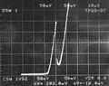
TD quick check example.jpg | TD quick check example.jpg | Tunnel diode quick check example using the method from Service Scope 49, April 1968. Right beam is zoomed with delayed timebase to show step speed. | ||
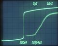
IV Ge TD-10mA.jpg | IV Ge TD-10mA.jpg | Tektronix [[571]] curve tracer I-V run of a 10 mA germanium tunnel diode | ||
TDA253-Tunnel_Diode.jpg | TDA253-Tunnel_Diode.jpg | TD 253 Tunnel Diode from a Tek 547 | ||
Tek_547-TunnelDiodes-Trigger.jpg | Tunnel Diodes TD253 and TD3A in a Tek 547 Trigger and Sweep Section) | Tek_547-TunnelDiodes-Trigger.jpg | Tunnel Diodes TD253 and TD3A in a Tek 547 Trigger and Sweep Section) | ||
Tunnel_DIode_1D2_2.2mA.jpg | 1D2 Tunnel Diode (2.2 mA) in a Tek 547 Delay Pickoff | Tunnel_DIode_1D2_2.2mA.jpg | 1D2 Tunnel Diode (2.2 mA) in a Tek 547 Delay Pickoff | ||
</gallery> | </gallery> | ||
Latest revision as of 06:29, 10 December 2023
Tunnel diodes (Esaki diodes) are used in various circuits in Tektronix gear made from the early 1960s until the 1980s.
Applications
Tunnel diodes were used where it was desirable to have fast and clean switching between two states. They were used in
- trigger circuits as Schmitt triggers,
- sweep and timing circuits as flip-flops,
- pulse generators for converting a slow-rise signals to fast-rise pulses,
- countdown/sync circuits
Issues of Drift and Failure
Tunnel diode characteristics (peak and valley voltages and currents) tend to drift. Usually this can be handled by adjusting the surrounding circuit. Sometimes tunnel diodes completely fail. Replacement usually involves scavenging a similar tunnel diode from some other device. There are some people in the Tek community who may have some tunnel diodes they can sell. Germanium tunnel diodes are extremely sensitive to overheat, especially at soldering work. Be aware and use low melting solder and appropriate tool to protect the body from overheating!
Relevant Distinguishing Parameters
Many different types of tunnel diodes were made. The primary parameter that describes one is the peak current, which is the current at the top of the hill in the I-V curve. The other two relevant electrical parameters are the capacitance of the diode and whether it is made of GaAs or Ge. In some circuits, another model of tunnel diode can be substituted with only minor modifications to the surrounding circuit. Stan Griffiths describes such a modification here:
Emulation using Common Parts
A common question is whether an electrical equivalent to a tunnel diode can be made out of modern, available parts. It is not hard to emulate the I-V curve, but there is no known circuit that can be made from available parts that has right I-V curve and the high switching speed of the real diode.
Testing a Tunnel Diode
Before concluding that a tunnel diode is bad, it is important to be sure that it has been measured correctly. A high resistance reading on a DMM indicates that the diode is bad. A low resistance on a DMM and a low voltage on a diode tester are both normal when measuring a tunnel diode. A more thorough test of a tunnel diode is to drive it through a resistor with a ramp voltage source while observing the voltage across the tunnel diode. The resistor should be calculated so that the peak current just exceeds the peak current that the tunnel diode is rated for. Of course if a curve tracer is available, it is great for measuring the I-V curve of the diode (note the negative-resistance part of the curve may not show due to the fast transit).
A short article in Service Scope 49, April 1968 describes a quick checking setup that approximates a curve tracer using the scope's X sawtooth output (see in photo section below).


Modeling
The fast switching action of the tunnel diode can be understood by modeling it as a nonlinear voltage controlled current source (VCCS) in parallel with a small parasitic capacitor. The nonlinear VCCS is controlled by the voltage at the terminals of the diode and is responsible for the S-shaped I-V curve. (Alternatively and equivalently, it can be modeled as nonlinear resistance. However, the nonlinear VCCS model might be preferable because it avoids the confusing notion of negative resistance.)
Consider a tunnel diode biased by a DC current source that is slowly brought up from zero to a current just a few microamperes less than the diode's peak current. The quiescent voltage will be just less than the peak voltage.
Note that the I-V curve is nearly horizontal at this point, and therefore the incremental resistance of the diode is very high at this point. For simplicity, we can assume that the incremental resistance is infinite at this quiescent point.

Estimating Switching Speed
Now that we have established the initial bias conditions, let's look at the event when the tunnel diode switches state. Assume that the triggering signal is coupled to the tunnel diode through a resistor. The current through the resistor adds to the current from the DC current source. Since we are assuming that the incremental resistance of the diode is infinite at the initial bias point, all of the current due to the trigger signal flows into and out of the diode's capacitance. If enough charge is added, the instantaneous voltage across the diode will be in the second region, where the slope of the VCCS function is negative.

Once the diode enters the second region, increases in diode voltage cause decreases in diode current. Applying Kirchhoff's current law at the node where the diode meets the DC current source, we can see that the current entering the parasitic capacitor at any instant is the difference between the DC current source and the nonlinear VCCS current at the this instantaneous voltage. We can use this fact to estimate the switching time of the tunnel diode. (The shape of the transition can also be estimated.)
As an example, let's take the case of a tunnel diode with 10 mA peak current and 5 pF capacitance. A first-order estimate of the switching time can be made by assuming that to make the transition from V1 to V2, a certain amount of charge needs to be added to the parasitic capacitance of the diode.
- From Q = C * V, we know that ∆ Q = C * ∆ V, which is ∆ Q = C * (V2 - V1)
- With V1 = 65 mV and V2 = 465 mV, ∆ Q = 5 * 10-12 F * 0.4 V = 2 picocoulombs.
Now we bravely assume that the charging current during the transition is constant, and is half of the peak current. 5 mA is 5 millicoulombs per second.
- t = (2 * 10-12 C) / (5 * 10-3 A) = 0.4 ns


Tunnel Diodes Used in Tektronix Instruments
- STD615 (152-01-02-00) - Ge, 10 mA, 28 pF
- TD1081 (152-0099-00) - Ge, 50 mA, 6 pF
- TD253 (152-0154-00) - Ge, 10 mA, 9 pF
- TD3A (152-0125-xx) - Ge, 4.7 mA, 18 pF
- 1N3129 - Ge, 20 mA, 20 pF
- 1N3130 - Ge, 50 mA, 6 pF
- 1N3712 - Ge, 1 mA ±10%, 10 pF
- 1N3713 - Ge, 1 mA ±2.5%, 5 pF
- 1N3714 - Ge, 2.2 mA ±10%, 25 pF
- 1N3715 - Ge, 2.2 mA ±2.5%, 10 pF
- 1N3716 - Ge, 4.7 mA ±5%, 50 pF
- 1N3717 - Ge, 4.7 mA ±2.5%, 25 pF
- 1N3718/TD4 - Ge, 10 mA ±10%, 90 pF
- 1N3719 - Ge, 10 mA ±2.5%, 25 pF
- 1N3720 - Ge, 22 mA ±10%, 150 pF
- 1N3721 - Ge, 22 mA ±2.5%, 100 pF
- 152-0140-01 - Ge(?), 10 mA, 8 pF
- 152-0177-00/-01/-02 - Ge, 10 mA, 4.7 pF
- 152-0181-00 - Ge(?), 1 mA, 5 pF
- 152-0182-00 - Ge(?), 10 mA, 50 pF
- 152-0254-01 - Ge, 100 mA, 6 pF
- 152-0329-00 - Ge(?), 19 mA, 1.5 pF
- 152-0379-00 - Ge(?), 20 mA, 10 pF
- 152-0383-00 - 50 mA, tr 31 ps
- 152-0386-00 - Ge(?), 10 mA, 25 pF
- 152-0402-00 - 2.2 mA 25 pF
- 152-0489-00 - Ge(?), 21 mA, 1.5 pF
- 153-0040-00 - 50 mA low-capacitance
- 153-0400-00 - 50 mA low-capacitance
Reading
Textbooks and references
- Wikipedia: Tunnel Diode / Backward Diode
- Millman and Taub Pulse, Digital and Switching Waveforms Chapters 12 and 13
- Sylvester P. Gentile: Basic Theory and Application of Tunnel Diodes (1962)
- Tunnel diode switching circuits and the back diode. Service Scope No. 38, June 1966 and No. 39, August 1966
- Article by General Radio on Tunnel Diode Measurements
- tpub.com: The Tunnel Diode
- AEC - NASA Tech Brief 69-10116 (1969): Simple Tunnel Diode Circuit for Accurate Zero Crossing Timing
- Nuclear Instruments and Methods 66 (1968): Inductance Effects on Capacitive Loading of a Tunnel Diode
- Andrews "Directional-Coupler Technique for Triggering a Tunnel Diode"
- Andrews and Nahman "Reference Waveform Flat Pulse Generator"
- Andrews "Improved Bias Supply for Tunnel-Diode Picosecond Pulse Generators"
- NASA Technical Note: Paull, Cancro, and Garrahan, "Low Power Nanosecond Pulse and Logic Circuits Using Tunnel Diodes"
- Rufus P. Turner, "Diode Circuits Handbook"
- American Micro Semiconductor: Tunnel Diode and Back Diode (archived webpage)
- Media:L'Archeveque-RV-1965-PhD-Thesis.pdf
Documents Referencing Tunnel diodes
| Document | Class | Title | Authors | Year | Links |
|---|---|---|---|---|---|
| Service Scope 49 Apr 1968.pdf | Article | Quick Check for Tunnel Diodes | Tony Bryan | 1968 | Tunnel diodes • 454 |
| 062-1009-00.pdf | Book | Measurement Concepts: Semiconductor Device Measurements | John Mulvey | 1969 | Curve tracers • Tunnel diodes |
| Tekscope 1970 V2 N2 Apr 1970.pdf | Article | Troubleshooting Sampling Systems | Charles Phillips | 1970 | Sampling • Tunnel diodes |
| Tekscope 1970 V2 N3 Jun 1970.pdf | Article | Troubleshooting Sampling Systems, Part 2 | Charles Phillips | 1970 | Tunnel diodes |
| Tekscope 1972 V4 N4 Jul 1972.pdf | Article | Tunnel Diodes: In-Circuit Testing Using the 7D13 Digital Multimeter Plug-In | 1972 | Tunnel diodes • 7D13 | |
| Tektronix Curve Tracers - Device Testing Techniques.pdf | Book | Tektronix Curve Tracers - Device Testing Techniques | 1985 | Curve tracers • Tunnel diodes |
Cross-reference
- Tektronix diode cross reference - Tunnel, Back, Four-layer, Varicap, Snap-off, Suppressor, PIN
- Craig Sawyers' 1N tunnel diode summary table
- Russian tunnel diodes
- See also Category:Tunnel diodes / Category:Back diodes
General Electric
- General Electric Tunnel Diode Manual, 1st ed. 1961
- General Electric Tunnel Diode Manual (1961)
- General Electric Transistor Manual (1964)
- GE TD26x/TD27x Datasheet
- General Electric Tunnel Diodes in 1966 Transistor Catalog (OCR)
- 1959 General Electric Research Information Services Report on Tunnel Diodes
- General Electric 1N3712 to 1N3721 Data
RCA
Other Manufacturers
- 1N3271 to 1N4399B Specs (PDF)
- Tunnel Diodes Section of 1961 D.A.T.A. book (full book: https://archive.org/details/DATASemiconductorDiodeRectifierCharacteristicsTabulation1961VolVII)
Images
-
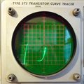
Testing a tunnel diode on a 575
-
Testing a tunnel diode with an audio oscillator and a 7D20 in X-Y mode
-
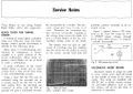
Tunnel diode quick check method, from Service Scope 49, April 1968
-
Tunnel diode quick check example using the method from Service Scope 49, April 1968. Right beam is zoomed with delayed timebase to show step speed.
-

Tektronix 571 curve tracer I-V run of a 10 mA germanium tunnel diode
-
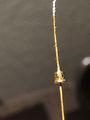
TD 253 Tunnel Diode from a Tek 547
-
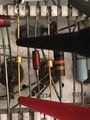
Tunnel Diodes TD253 and TD3A in a Tek 547 Trigger and Sweep Section)
-
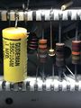
1D2 Tunnel Diode (2.2 mA) in a Tek 547 Delay Pickoff


