Uploads by Aobp11
Jump to navigation
Jump to search
This special page shows all uploaded files.
| Date | Name | Thumbnail | Size | Description | Versions |
|---|---|---|---|---|---|
| 12:34, 25 August 2022 | 7633-A10board-B20up.jpg (file) |  |
47 KB | 1 | |
| 10:36, 25 August 2022 | 7633-A10-B20up.jpg (file) |  |
222 KB | 1 | |
| 12:44, 10 December 2021 | 067-0650-00 topleft.jpg (file) |  |
65 KB | 1 | |
| 12:12, 10 December 2021 | 067-0650-00 top.jpg (file) |  |
74 KB | Overview from top | 1 |
| 12:11, 10 December 2021 | 067-0650-00 topfront.jpg (file) |  |
64 KB | View at oscillator drive | 1 |
| 12:09, 10 December 2021 | 067-0650-00 rightfront.jpg (file) |  |
61 KB | View at switches and VAR pot | 1 |
| 12:07, 10 December 2021 | 067-0650-00 regulator.jpg (file) |  |
56 KB | Left side with regulator board | 1 |
| 12:06, 10 December 2021 | 067-0650-00 power.jpg (file) |  |
57 KB | Power supply with pre-regulator board | 1 |
| 12:03, 10 December 2021 | 067-0650-00 junctionbox.jpg (file) |  |
42 KB | Junction box with inputs from 9 MHz and 220-900 MHz oscillators | 1 |
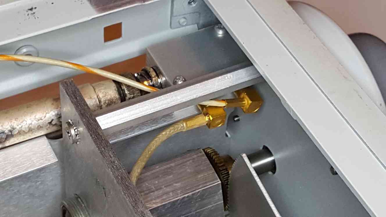
| 12:01, 10 December 2021 | 067-0650-00 filter&knees.jpg (file) |  |
51 KB | Filter input connected to oscillator cable via 3 BNC knees | 1 |
| 11:58, 10 December 2021 | 067-0650-00 filter&junctionbox.jpg (file) |  |
47 KB | Filter connected to junction box | 1 |
| 05:14, 17 August 2021 | Time-base-knob.jpg (file) |  |
27 KB | Time base knob with sleeve | 1 |
| 05:10, 1 April 2021 | P6302 plugcap unscrewed.jpg (file) |  |
13 KB | Plug cap unscrewed. Sleeve pulled out a few mm. | 1 |
| 08:54, 31 March 2021 | A6302 printje.jpg (file) | 55 KB | A6302 Component view | 1 | |
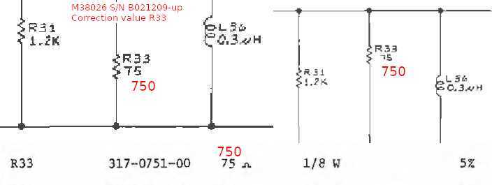
| 03:36, 24 March 2021 | 7M11 schem corr.jpg (file) |  |
13 KB | Correction value R33 | 1 |
| 08:59, 10 January 2021 | P6451-Terminals.jpg (file) |  |
47 KB | Lead terminals which go into connector block#redirect[[]] | 1 |
| 08:06, 26 September 2020 | 070-0382-02.pdf (file) |  |
19.5 MB | 502A/RM502A (late) Instruction manual | 1 |
| 11:23, 23 September 2020 | 070-0382-02 partial.pdf (file) |  |
2.12 MB | Partial 502A (late) Instruction manual. Contains 3 diagrams and the relevant Calibration Procedure pages. | 2 |
| 09:52, 31 August 2017 | Tek-7704A-Interconnect-2.jpg (file) |  |
168 KB | Interconnect plug in temporary store location | 1 |
| 09:50, 31 August 2017 | Tek-7704A-Interconnect-1.jpg (file) |  |
345 KB | Interconnect plug in normal position | 1 |
| 12:53, 18 January 2015 | 564 (3).jpg (file) | .jpg) |
41 KB | 564 version 3 | 1 |
| 12:52, 18 January 2015 | 564 (2).jpg (file) | .jpg) |
39 KB | 564 version 2 | 1 |
| 12:51, 18 January 2015 | 564 (1).jpg (file) | .jpg) |
37 KB | 564 Front panel version 1 | 1 |
| 08:20, 10 January 2015 | PSA225 Right.jpg (file) |  |
377 KB | Right side Nelson_Ross PSA 225. | 1 |
| 08:19, 10 January 2015 | PSA225 Left.jpg (file) |  |
481 KB | Left side Nelson-Ross PSA 225. | 1 |
| 08:17, 10 January 2015 | PSA225 Front.jpg (file) |  |
204 KB | Front van Nelson-Ross PSA 225. | 1 |
| 14:25, 9 January 2015 | PSA225.pdf (file) |  |
2.32 MB | The last pages of the manual describe the modification need for the early versions of time bases 67, 2B67, 3B1, 3B3 and 3B4. | 1 |