3S76: Difference between revisions
m (→top: clean up, replaced: title=Tektronix → manufacturer=Tektronix |series=560-series scopes |type=, {{Plugin Sidebar 2 → {{Plugin Sidebar, series=560-series scopes → designers=) |
No edit summary |
||
| Line 10: | Line 10: | ||
|discontinued=(?) | |discontinued=(?) | ||
|manuals= | |manuals= | ||
* [ | * [[Media:070-332.pdf|Tektronix 3S76 Manual]] (PDF) | ||
* [http://w140.com/tek_3s76_schematics.pdf Tektronix 3S76 Schematics (PDF)] | * [http://w140.com/tek_3s76_schematics.pdf Tektronix 3S76 Schematics (PDF)] | ||
* [[Media:Tek 3s76 cal outline.pdf|Tektronix 3S76 Calibration Outline (PDF, OCR)]] | * [[Media:Tek 3s76 cal outline.pdf|Tektronix 3S76 Calibration Outline (PDF, OCR)]] | ||
Revision as of 10:19, 15 August 2021

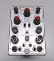
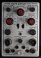
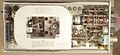
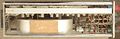
The Tektronix 3S76 is a dual-trace sampling plug-in for 560-series scopes. The inputs have 50 Ω impedance and use GR-874 connectors. Rise time is rated at less than 0.4 ns.
The initial design work on the 3S76 was done by Cliff Moulton. It was called the Type 76, later renamed 3S76 before going into production. A decision was made to demonstrate the 76/3S76 at the 1961 IRE show. This created a panic because the plug-in was not complete. The 76 project landed in the TV group. Ron Olson and Charlie Rhodes were designing it and Walt Lowy was a technician. Phil Crosby worked on it for a week during spring break from Portland State (college then, not university). Phil Crosby designed the channel switching circuitry.
Key Specifications
| Rise time | < 400 ps |
|---|---|
| Bandwidth | 875 MHz |
| Input impedance | 50 Ω |
| Triggering | Internal trigger take-off, 55 ns delay line |
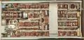
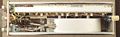
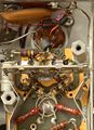
Internals
Each input has a trigger takeoff transformer and a 55 ns coaxial delay line. The trigger source channel is selectable.
Each delay line terminates at that channel's sampling bridge, which is a four-diode design using beam-lead GaAs diodes.
A 7586 nuvistor buffers the output of each sampling bridge. The sampling pulse, common to both channels, is generated by a 152-115 snap-off diode and a 3 cm twisted-pair clipping line.
Pictures
-
front
-
-
-
-
-
-
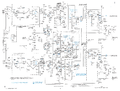
Sampler schematic
-