11A32: Difference between revisions
No edit summary |
(Removed some redundancies) |
||
| Line 17: | Line 17: | ||
}} | }} | ||
The '''Tektronix 11A32''' is a 400 MHz dual-channel amplifier plug-in for [[11000-series scopes]]. | The '''Tektronix 11A32''' is a 400 MHz dual-channel amplifier plug-in for [[11000-series scopes]]. | ||
{{BeginSpecs}} | |||
{{Spec | Bandwidth | DC to 400 MHz; 100 MHz and 20 MHz BWL filters }} | |||
{{Spec | Rise time | 875 ps in 1 GHz mainframes such as the [[11402]], [[11402|11402A]], [[11403]], [[11403|11403A]], [[DSA600|DSA601A]], or [[DSA600|DSA602A]]}} | |||
{{Spec | Deflection | 1 mV to 10 V per division in 1% calibrated steps}} | |||
{{Spec | Input impedance | 50 Ω or 1 MΩ }} | |||
{{Spec | Features | | |||
* High-resolution calibrated DC offset | |||
* Fast overdrive recovery | |||
* 5 V<sub>RMS</sub> overload protection in 50 Ω mode, with manual reset | |||
}} | |||
{{EndSpecs}} | |||
==Internals== | |||
===Analog=== | |||
Each input channel has a separate attenuator modules containing an [[M474]] buffer amplifier, | |||
feeding an [[M377]] amplifier IC, one per input channel. | |||
The display outputs of the two M377s are hard-wired in parallel and drive the mainframe’s | |||
The display outputs of the two | 50 Ω input impedance. The same is true of the trigger outputs of the two amplifiers. | ||
The same is true of the trigger outputs of the two amplifiers. | |||
The version of the M377 used in the 11A32 has 100 Ω output impedance so that two of them in parallel create a source impedance of 50 Ω. | The version of the M377 used in the 11A32 has 100 Ω output impedance so that two of them in parallel create a source impedance of 50 Ω. | ||
Each M377 amplifier's nominal common-mode output voltage is zero whether enabled or not. | Each M377 amplifier's nominal common-mode output voltage is zero whether enabled or not. | ||
When not enabled each M377 differential output is exactly zero by design. | When not enabled, each M377 differential output is exactly zero by design. | ||
This fact is used during calibration by the plugin’s firmware to determine the mainframe’s imbalance and compensate for it during normal operation. | This fact is used during calibration by the plugin’s firmware to determine the mainframe’s imbalance and compensate for it during normal operation. | ||
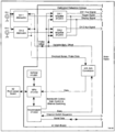
See also the block diagram below. | |||
===Digital=== | |||
The 11A32 and the [[11A34]] use exactly the same firmware. | |||
The 11A32 and [[11A34]] were originally intended to use [[Intel 8052]] microcontrollers. | The 11A32 and [[11A34]] were originally intended to use [[Intel 8052]] microcontrollers. | ||
However, during development, the firmware swelled beyond that chip's 8192-byte maximum on-chip ROM size. | However, during development, the firmware swelled beyond that chip's 8192-byte maximum | ||
[[Doug Haines]] found an alternate supplier of 8051-compatible chips (OKI Semiconductor) that offered a 16Kbyte on-chip ROM, | on-chip ROM size. [[Doug Haines]] found an alternate supplier of 8051-compatible chips | ||
and that's what the plug-ins wound up with. The finished code size wound up at about 14 KB. | (OKI Semiconductor) that offered a 16Kbyte on-chip ROM, and that's what the plug-ins | ||
wound up with. The finished code size wound up at about 14 KB. | |||
The 11A32 also contains a DS1120 NVRAM and an [[ACVS]] | The 11A32 also contains a DS1120 NVRAM and an [[ACVS]] module that generates the analog control voltages needed for gain/offset control etc. | ||
==Links== | ==Links== | ||
Revision as of 05:45, 31 December 2022

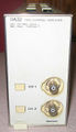
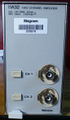
The Tektronix 11A32 is a 400 MHz dual-channel amplifier plug-in for 11000-series scopes.
Key Specifications
| Bandwidth | DC to 400 MHz; 100 MHz and 20 MHz BWL filters |
|---|---|
| Rise time | 875 ps in 1 GHz mainframes such as the 11402, 11402A, 11403, 11403A, DSA601A, or DSA602A |
| Deflection | 1 mV to 10 V per division in 1% calibrated steps |
| Input impedance | 50 Ω or 1 MΩ |
| Features |
|
Internals
Analog
Each input channel has a separate attenuator modules containing an M474 buffer amplifier, feeding an M377 amplifier IC, one per input channel.
The display outputs of the two M377s are hard-wired in parallel and drive the mainframe’s 50 Ω input impedance. The same is true of the trigger outputs of the two amplifiers. The version of the M377 used in the 11A32 has 100 Ω output impedance so that two of them in parallel create a source impedance of 50 Ω.
Each M377 amplifier's nominal common-mode output voltage is zero whether enabled or not.
When not enabled, each M377 differential output is exactly zero by design. This fact is used during calibration by the plugin’s firmware to determine the mainframe’s imbalance and compensate for it during normal operation.
See also the block diagram below.
Digital
The 11A32 and the 11A34 use exactly the same firmware.
The 11A32 and 11A34 were originally intended to use Intel 8052 microcontrollers. However, during development, the firmware swelled beyond that chip's 8192-byte maximum on-chip ROM size. Doug Haines found an alternate supplier of 8051-compatible chips (OKI Semiconductor) that offered a 16Kbyte on-chip ROM, and that's what the plug-ins wound up with. The finished code size wound up at about 14 KB.
The 11A32 also contains a DS1120 NVRAM and an ACVS module that generates the analog control voltages needed for gain/offset control etc.
Links
Pictures
-
-
-
Block diagram
-
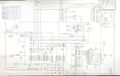
11A32 Main Board Schematic
-
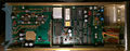
11A32 Main Interface
-
left side internal
-
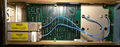
right side internal


Custom ICs used in the 11A32
| Page | Model | Part nos | Description | Designers | Used in |
|---|---|---|---|---|---|
| M377 | M377 | 165-2129-03 • 165-2089-06 • 155-2089-05 | amplifier | John Addis | 11A16 • 11A32 • 11A33 • 11A34 • 11A52 • 2245 • 2245A • 2247 • 2247A • 2252 • TDS410 • TDS420 • TDS460 • TDS520D • TDS540D • TDS580D • TDS680C • TDS684C • TDS714L • TDS724D • TDS754D • TDS784D |
| M474 | M474 | amplifier | John Addis • Ivan John Cousins | 11A32 • 11A34 |