2A61: Difference between revisions
No edit summary |
No edit summary |
||
| (10 intermediate revisions by 3 users not shown) | |||
| Line 1: | Line 1: | ||
{{Plugin Sidebar | {{Plugin Sidebar | ||
| manufacturer=Tektronix | |||
summary = Differential amplifier | | | series=560-series scopes | ||
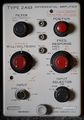
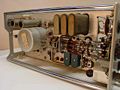
image=Tek 2a61 front.jpg| | | type= 2A61 | ||
caption= | | summary = Differential amplifier plug-in | ||
| image=Tek 2a61 front.jpg | |||
introduced=1963 | | | caption=Tektronix 2A61 Front | ||
discontinued=(?) | | | designers=Larry Mayhew | ||
manuals= | | introduced=1963 | ||
* [ | | discontinued=(?) | ||
* [ | | manuals= | ||
* [[Media:070-0328-01.pdf|Tektronix 2A61 Manual]] (OCR) | |||
* [[Media:2a61 1000-1 cal input adapter.pdf|Tektronix 2A61 1000:1 Cal Div/Input Adapter (OCR)]] | |||
}} | }} | ||
The '''Tektronix 2A61''' is a differential amplifier plug-in for [[560-series scopes]] | The '''Tektronix 2A61''' is a high gain differential AC amplifier plug-in for the [[560-series scopes | 560 series oscilloscopes]], [[introduced in 1963]]. It has independently switchable low frequency and high frequency limits. The low frequency limit can go well below 1 Hz, but it can't go to DC. | ||
{{BeginSpecs}} | |||
{{Spec | Input impedance | 1 MΩ // ~100 pF }} | |||
{{Spec | Deflection | 10 μV/div to 20 mV/div in 1−2−5 sequence }} | |||
{{Spec | Bandwidth | Switch selectable:<br>Low Limit: ~0.06 to ~600 Hz<br>High Limit: ~60 Hz to ~0.3 MHz }} | |||
{{Spec | CMRR | 50,000:1 at Frequencies below 10 kHz }} | |||
{{Spec | Common Mode Range | -5 V to 5 V in A-B mode}} | |||
{{Spec | Input DC Bias | Max: ±0.1 V differential }} | |||
{{Spec | Line Filter | Switchable: at Least 50:1 attenuation }} | |||
{{EndSpecs}} | |||
==Internals== | ==Internals== | ||
The front end consists of a differential amplifier. | The front end consists of a differential amplifier. | ||
Up to serial number 986, the front-end differential amplifier | Up to serial number 986, the front-end differential amplifier used a pair of [[5842]] tubes biased with a tail current of 10 mA and a plate-to-cathode voltage of about 100 V. | ||
used a pair of [[5842]] tubes biased with a tail current of | |||
plate-to-cathode voltage of about | |||
[[File:2a61 frontend.png|thumb|left|upright|[[Nuvistor]]-based front-end amplifier]] | [[File:2a61 frontend.png|thumb|left|upright|[[Nuvistor]]-based front-end amplifier]] | ||
Starting with serial number 987, the front-end differential amplifier | Starting with serial number 987, the front-end differential amplifier was made with four [[7586]] [[nuvistor]] triodes: V424, V425, V524, and V525. | ||
was made with four [[7586]] [[nuvistor]] triodes: V424, V425, V524, and V525. | |||
The parallel combination of V424 and V425 forms one side of the differential amplifier | The parallel combination of V424 and V425 forms one side of the differential amplifier and the parallel combination of V524 and V525 forms the other side. | ||
and the parallel combination of V524 and V525 forms the other side. | However, for purposes of thermal stability, V424 is thermally connected to V524 and V425 is thermally connected to V525. | ||
However, for purposes of thermal stability, V424 is thermally connected to V524 | The tail current in the 987-and-up version is about 16 mA and the nuvistors have a plate-to-cathode voltage of about 70 V. | ||
and V425 is thermally connected to V525. | |||
The tail current in the 987-and-up version is about 16 mA | |||
and the nuvistors have a plate-to-cathode voltage of about | |||
The second gain stage is a differential amplifier made of a pair of a pair of germanium PNP transistors. | The second gain stage is a differential amplifier made of a pair of a pair of germanium PNP transistors. | ||
To implement the low-frequency cutoff, | To implement the low-frequency cutoff, the 2A61 has a large electrolytic capacitor, C437 (13,000 μF or 20,000 μF depending on serial number), | ||
the 2A61 has a large electrolytic capacitor, | in the emitter frequency compensation network of the second differential amplifier stage. | ||
C437 (13,000 μF or 20,000 μF depending on serial number), | |||
in the emitter frequency compensation network | |||
of the second differential amplifier stage. | |||
Although C437 is polarized, it is operated with no DC bias | Although C437 is polarized, it is operated with no DC bias and therefore sees reverse voltage as part of normal operation. | ||
and therefore sees reverse voltage as part of normal operation. | D437 and D438 shunt C437, preventing it from ever seeing a voltage more than one diode drop. | ||
D437 and D438 shunt C437, preventing it from ever seeing a voltage | Most electrolytic capacitors are specified to handle reverse voltages of at least 1 V without damage. | ||
more than one diode drop. Most electrolytic capacitors are specified | |||
to handle reverse voltages of at least | |||
The 2A61 manual's calibration instructions recommend using the Heathkit IG-72 | The 2A61 manual's calibration instructions recommend using the Heathkit IG-72 Audio Generator. | ||
Audio Generator. | |||
A suitable input connector for the 2A61 is a PC06 8-4P / MS3106 8-4P. | |||
The standard cable for connecting the input signal to the 2A61 is the [[012-072]]. | |||
==Pictures== | ==Pictures== | ||
<gallery> | <gallery> | ||
Tek 2a61 front.jpg|Front | Tek 2a61 front.jpg | Front | ||
Tek 2a61 left.jpg|Left | Tek 2a61 left.jpg | Left | ||
Tek 2a61 right.jpg|Right | Tek 2a61 right.jpg | Right | ||
Tek 2a61 top.jpg|Top | Tek 2a61 top.jpg | Top | ||
Tek 2a61 bottom.jpg|Bottom | Tek 2a61 bottom.jpg | Bottom | ||
Tek 2a61 1.jpg | Tek 2a61 1.jpg | ||
Tek 2a61 2.jpg | Tek 2a61 2.jpg | ||
Tek 2a61 3.jpg | Tek 2a61 3.jpg | ||
Tek 2a61 4.jpg | Tek 2a61 4.jpg | ||
Tek-2a61 early.png|Schematic (early version) | Tek-2a61 early.png | Schematic (early version) | ||
Tek-2a61 late.png|Schematic (late version) | Tek-2a61 late.png | Schematic (late version) | ||
</gallery> | </gallery> | ||
[[Category:560 series plugins]] | [[Category:560 series plugins]] | ||
Latest revision as of 08:03, 10 March 2024

The Tektronix 2A61 is a high gain differential AC amplifier plug-in for the 560 series oscilloscopes, introduced in 1963. It has independently switchable low frequency and high frequency limits. The low frequency limit can go well below 1 Hz, but it can't go to DC.
Key Specifications
| Input impedance | 1 MΩ // ~100 pF |
|---|---|
| Deflection | 10 μV/div to 20 mV/div in 1−2−5 sequence |
| Bandwidth | Switch selectable: Low Limit: ~0.06 to ~600 Hz High Limit: ~60 Hz to ~0.3 MHz |
| CMRR | 50,000:1 at Frequencies below 10 kHz |
| Common Mode Range | -5 V to 5 V in A-B mode |
| Input DC Bias | Max: ±0.1 V differential |
| Line Filter | Switchable: at Least 50:1 attenuation |
Internals
The front end consists of a differential amplifier. Up to serial number 986, the front-end differential amplifier used a pair of 5842 tubes biased with a tail current of 10 mA and a plate-to-cathode voltage of about 100 V.

Starting with serial number 987, the front-end differential amplifier was made with four 7586 nuvistor triodes: V424, V425, V524, and V525.
The parallel combination of V424 and V425 forms one side of the differential amplifier and the parallel combination of V524 and V525 forms the other side. However, for purposes of thermal stability, V424 is thermally connected to V524 and V425 is thermally connected to V525. The tail current in the 987-and-up version is about 16 mA and the nuvistors have a plate-to-cathode voltage of about 70 V.
The second gain stage is a differential amplifier made of a pair of a pair of germanium PNP transistors. To implement the low-frequency cutoff, the 2A61 has a large electrolytic capacitor, C437 (13,000 μF or 20,000 μF depending on serial number), in the emitter frequency compensation network of the second differential amplifier stage.
Although C437 is polarized, it is operated with no DC bias and therefore sees reverse voltage as part of normal operation. D437 and D438 shunt C437, preventing it from ever seeing a voltage more than one diode drop. Most electrolytic capacitors are specified to handle reverse voltages of at least 1 V without damage.
The 2A61 manual's calibration instructions recommend using the Heathkit IG-72 Audio Generator.
A suitable input connector for the 2A61 is a PC06 8-4P / MS3106 8-4P. The standard cable for connecting the input signal to the 2A61 is the 012-072.
Pictures
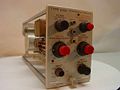
-
Front
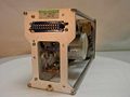
-
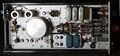
Left
-
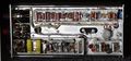
Right
-
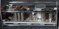
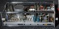
Top
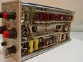
-
Bottom
-
-
-
-
-
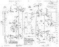
Schematic (early version)
-
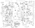
Schematic (late version)


