492

The Tektronix 492 is a spectrum analyzer with a frequency range of 10 kHz to 21 GHz in coax, and up to 325 GHz with external waveguide mixers (492PGM N/A). The P suffix designation indicates GPIB Programmability.
During the lifespan of the instrument, the specifications and included options were altered several times. A major upgrade was the introduction of the 492A in 1987 which added marker functionality and resolution bandwidths and the 492BP in 1989 which added a counter and increased the displayed dynamic range. The 492PGM is a cost reduced version introduced in 1990. Also see 49X Series Comparison.
Key Specifications
| Frequency |
|
|---|---|
| Frequency Span | 492BP: 100 Hz/div to 10 GHz/div; 492PGM: 200 MHz to 1 GHz; both in 1, 2, 5 sequence; plus 0 Hz and MAX |
| Resolution Bandwidth (-6 dB bandwidth) | 492BP: 100 Hz to 3 MHz; 492PGM: 1 kHz to 3 MHz; both in decade steps |
| RF Input | 50 Ω, max. +30 dBm (1 W) CW; / 75 W peak pulse (1 µs, 0.1% duty factor) |
| RF Attenuator | 0 dB to 60 dB, 10 dB steps |
| Reference Level | -117 dBm to +30 dBm |
| Sweep Speed | 10 sec/div to 20 µs/div, 1−2−5 |
| Video Bandwidth | 492BP: 0.3 Hz to 30 kHz; 492PGM: 3 Hz to 30 kHz |
| Memory | NVRAM for up to 9 waveform displays, up to 10 front panel setups, plus 8 K for programming macros |
| Triggering Modes | Free Run, Line, Video, Single, External |
| Displayed Average Noise | −30 dBm to −131 dBm |
| Display Dynamic Range | 492BP: 90 dB; 492PGM: 80 dB |
| Calibrator (Cal out) | 50 Ω, -20 dBm ±0.3 dB at 100 MHz |
| Weight | 492BP: 21.8 kg (47 lbs) 492PGM: 21.3 kg (46 lbs) |
| Power | 90 − 132 VAC, 48 to 440 Hz; 180 – 250 VAC, 48 to 440 Hz. At 115 VAC, 60 Hz, 210 W max |
Options
- Opt. 01: Internal Preselection. (Limits the first band to 1.8 GHz instead 4.2 GHz). Later became standard
- Opt. 02: Digital Storage. Later became standard
- Opt. 03: Frequency Stabilization & 100 Hz Resolution. Later became standard
- Opt. 07: 75 Ω dBmV input and calibration in addition to the normal 50 Ω dBm input and calibration. (Not combinable with Opt. 21 and 22; no external mixer capability). Include 42-inch 75 Ω BNC-BNC coax cable and BNC male to “F” female adapter.
- Opt. 21: (492BP) High performance 18 to 40 GHz WM490 Series Waveguide Mixer Set
- Opt. 22: (492BP) Same as Opt. 21 plus WM490U (40-60 GHz) Waveguide Mixer
- Opt. 23: GRASP software, PC2A interface, and GPIB cable
- Opt. 27: Epson LT-386SX, GRASP software, PC2A interface, and GPIB cable
- Opt. 28: Compaq Deskpro 386S, Model 40, GRASP software, PC2A interface, and GPIB cable
- Opt. 39: Non-lithium (Silver) batteries for battery-backed memory
- Opt. 41: Digital Microwave Radio Measurement Enhancement package
- Opt. 42: Replaces MARKER/VIDEO input port on the rear panel with a 110 MHz IF output port that provides a 3 dB signal bandwidth ≥ 4.5 MHz
- Opt. 45: (all except 492PGM) MATE/CIIL language interface
Links
- Comparison of 492 with 494 and 7L18
- 49x Service notes @ John Miles KE5FX
- KE5FX GPIB toolkit
- ROM replacement
- Tek 492 DIY USB interface project
- Waveguide Mixers for 492 and 7L18
- YouTube: Tektronix 492 and 496 Portable Spectrum Analyzers
- 067-1137-99 GPIB to accessory controller
Documents Referencing 308
| Document | Class | Title | Authors | Year | Links |
|---|---|---|---|---|---|
| Tekscope 1980 V12 N1.pdf | Article | New Products | 1980 | 308 • SG505 • 8002A | |
| Tekscope 1980 V12 N2.pdf | Article | Portable Analyzer Speeds Test and Service of Microprocessor-Based System | Ed Averill • John Huber | 1980 | 308 |
Connections
Front panel inputs/outputs are:
- RF INPUT (50 Ω N connector) – Input for RF signals to 21 GHz. If input signal has a DC component, use a blocking capacitor
- CAL OUT (BNC connector) – Provides 100 MHz, –20 dBm signal and a comb of frequency markers 100 MHz apart
- 1ST LO OUTPUT (SMA connector) – Output of the 1st local oscillator, must be terminated into 50 Ω when not connected.
- 2ND LO OUTPUT (SMA connector) – Output of the 2nd local oscillator, must be terminated into 50 Ω when not connected.
- EXTERNAL MIXER RF INPUT (TNC connector, 50 Ω)
- Camera Power
Rear panel inputs/outputs are:
- PROBE POWER – Provides operating voltages (+5 V, -15 V, +15 V; 100 mA max each) for active probes
- HORIZ/TRIG (input, BNC) – In External Triggering mode, AC coupled input for trigger signals; when TIME/DIV selection is EXT, DC coupled input for horizontal sweep voltages
- MARKER/VIDEO (B053575+, output, BNC) – interfaces the 492/492P with a TV Sideband Adapter, such as the Tek 1405, so a marker from the adapter is displayed on the internal video. External video applied to this connector will also be displayed if pin 1 of the ACCESSORIES connector is grounded.
- Opt. 42 replaces MARKER/VIDEO with 110 MHz IF (output, BNC) – 3 dB signal bandwidth ≥ 4.5 MHz
- EXT PRESELECTOR (B053574 and below) (output, BNC) – variable voltage (approx -0.2 V to +10 V) proportional to center frequency, for preselector bands of Opt. 01 instruments, to drive an external preselector
- HORIZ (output, BNC) – 0.5 V/div horizontal signal
- VERT (output, BNC) – Video signal with 0.5 V/Div
- PEN LIFT (output, BNC) – TTL compatible signal to lift the pen of a chart recorder during sweep retrace. In Opt. 42 instruments this port may also be used for inputting external video if pin 1 of the ACCESSORY connector is grounded.
- 10 MHz IF (output, BNC) – Output of the 10 MHz IF
- J104 ACCESSORY (B053575+ only), female DB25 connector – Provides bidirectional access to the instrument bus.
- IEEE STD 488 PORT GPIB interface – Added to all "P" suffixed instruments
Pictures
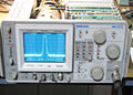
492
-
-
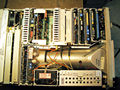
Internal top view


