565: Difference between revisions
(template, cat) |
|||
| Line 1: | Line 1: | ||
The Tektronix Type 565 is a [[dual-beam scopes|dual-beam scope]] that takes two [[2-series or 3-series vertical plug-ins]]. | {{Oscilloscope Sidebar | | ||
title=Tektronix 565 | | |||
image=Wellenkino 565.jpg | | |||
caption=Tektronix 565 | | |||
years=1963 — ? | | |||
summary=Dual-beam scope | | |||
manuals= | |||
* [http://bama.edebris.com/download/tek/565/565.djvu Tektronix 565 Manual (DjVu)] | |||
* [http://w140.com/tek_565.pdf Tektronix 565 Manual (PDF)] | |||
}} | |||
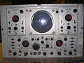
The '''Tektronix Type 565''' is a [[dual-beam scopes|dual-beam scope]] that takes two [[2-series or 3-series vertical plug-ins]]. | |||
It was [[introduced in 1963]]. | It was [[introduced in 1963]]. | ||
A rackmount version, the RM565, was also produced. Aside from being dual-beam, the 565 is unusual among the | |||
other [[560-series scopes]] in the fact that it (the mainframe) has built-in trigger, sweep, and horizontal amplifier circuits. | |||
==Specifications== | |||
''please add'' | |||
==Circuits== | |||
The 565 uses the [[T5650]] CRT. | |||
== Vertical Signal Path == | ===Vertical Signal Path=== | ||
As is usual for [[560-series scopes]], the vertical deflection plates of the CRT | As is usual for [[560-series scopes]], the vertical deflection plates of the CRT | ||
are driven directly, differentially, by pins 17 and 21 of the vertical plug-in. | are driven directly, differentially, by pins 17 and 21 of the vertical plug-in. | ||
The left plug-in bay is for the lower beam and the right plug-in bay is for the upper beam. | The left plug-in bay is for the lower beam and the right plug-in bay is for the upper beam. | ||
A 0. | |||
A 0.7—3 pF trimmer capacitor is connected immediately behind each of the plug-in connectors, and allows | |||
for the mainframe to be calibrated so that plug-ins can be interchanged without requiring the | for the mainframe to be calibrated so that plug-ins can be interchanged without requiring the | ||
high-frequency compensation of the system to be readjusted. | high-frequency compensation of the system to be readjusted. | ||
The capacitance seen by the plug-in driving the scope should be 14. | The capacitance seen by the plug-in driving the scope should be 14.3 pF for either beam. | ||
There is no trigger pickoff in the vertical signal path of the 565. That function is performed by the plug-ins. | There is no trigger pickoff in the vertical signal path of the 565. That function is performed by the plug-ins. | ||
=== Trigger and Sweep === | |||
== Trigger and Sweep == | |||
The triggering signal comes from pin 11 on the plug-ins, is amplified by a [[12AT7]]-based cathode follower, | The triggering signal comes from pin 11 on the plug-ins, is amplified by a [[12AT7]]-based cathode follower, | ||
and sent to "TRIGGER" switches. From there, the trigger signal is sent through a [[6DJ8]]-based differential amplifier | and sent to "TRIGGER" switches. From there, the trigger signal is sent through a [[6DJ8]]-based differential amplifier | ||
| Line 27: | Line 41: | ||
The sweep delay can be adjusted over a range from 10 microseconds to 50 seconds. | The sweep delay can be adjusted over a range from 10 microseconds to 50 seconds. | ||
The 565 is also unusual in that it employs a [[tunnel diodes|tunnel diode]] in the trace intensification circuit. The tunnel diode | The 565 is also unusual in that it employs a [[tunnel diodes|tunnel diode]] in the trace intensification circuit. The tunnel diode forms as a bistable multivibrator: kick it one way and it turns on and stays on, kick it the other way and | ||
forms as a bistable multivibrator: kick it one way and it turns on and stays on, kick it the other way and | |||
it turns off and stays off. | it turns off and stays off. | ||
=== Calibrator === | |||
== Calibrator == | The internal calibrator produces a 1 kHz square wave with amplitude selectable in decade steps from 1 mV to 100 V. | ||
The internal calibrator produces | |||
in decade steps from | |||
It is an astable multivibrator formed by one half of a [[12AT7]] and a [[6AU6]]. | It is an astable multivibrator formed by one half of a [[12AT7]] and a [[6AU6]]. | ||
The other half of the 12AT7 serves as the output cathode follower for the calibrator. | The other half of the 12AT7 serves as the output cathode follower for the calibrator. | ||
== Comparison with the [[556]] == | == Comparison with the [[556]] == | ||
The 565 appears similar to the [[556]], but is different in many ways. | The 565 appears similar to the [[556]], but is different in many ways. | ||
The 556 uses tunnel diodes for triggering, while the 565 uses tubes. | The 556 uses tunnel diodes for triggering, while the 565 uses tubes. | ||
The 556 uses [[letter-series and 1-series plug-ins]] while the 565 uses 560-series plug-ins. | |||
while the 565 uses 560-series plug-ins. | Moreover, the bandwidth of the 556 is specified as 50 MHz, while the bandwidth of the 565 is specified as 10 MHz. | ||
Subjectively, the trace of the 565 is very sharp, sharper than the trace of the 556. | |||
while the bandwidth of the 565 is specified as | |||
Subjectively, the trace of the 565 is very sharp, | |||
sharper than the trace of the 556. | |||
==Pictures== | |||
<gallery> | <gallery> | ||
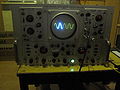
File:Rm565_1.jpg|Front from RM565 | |||
File:Rm565_2.jpg | |||
File:IMG 1213.JPG| Open 565 | |||
File:Wellenkino 565.jpg | File:Wellenkino 565.jpg | ||
File:RM565_P7.jpg|RM565 with P7 CRT | |||
</gallery> | </gallery> | ||
| Line 68: | Line 69: | ||
[[Category:Specifications needed]] | [[Category:Specifications needed]] | ||
[[Category:Introduced in 1963]] | |||
Revision as of 04:36, 17 August 2014

The Tektronix Type 565 is a dual-beam scope that takes two 2-series or 3-series vertical plug-ins.
It was introduced in 1963.
A rackmount version, the RM565, was also produced. Aside from being dual-beam, the 565 is unusual among the other 560-series scopes in the fact that it (the mainframe) has built-in trigger, sweep, and horizontal amplifier circuits.
Specifications
please add
Circuits
The 565 uses the T5650 CRT.
Vertical Signal Path
As is usual for 560-series scopes, the vertical deflection plates of the CRT are driven directly, differentially, by pins 17 and 21 of the vertical plug-in. The left plug-in bay is for the lower beam and the right plug-in bay is for the upper beam.
A 0.7—3 pF trimmer capacitor is connected immediately behind each of the plug-in connectors, and allows for the mainframe to be calibrated so that plug-ins can be interchanged without requiring the high-frequency compensation of the system to be readjusted. The capacitance seen by the plug-in driving the scope should be 14.3 pF for either beam.
There is no trigger pickoff in the vertical signal path of the 565. That function is performed by the plug-ins.
Trigger and Sweep
The triggering signal comes from pin 11 on the plug-ins, is amplified by a 12AT7-based cathode follower, and sent to "TRIGGER" switches. From there, the trigger signal is sent through a 6DJ8-based differential amplifier and then is discriminated by a 6DJ8-based Schmitt trigger.
The sweep delay can be adjusted over a range from 10 microseconds to 50 seconds.
The 565 is also unusual in that it employs a tunnel diode in the trace intensification circuit. The tunnel diode forms as a bistable multivibrator: kick it one way and it turns on and stays on, kick it the other way and it turns off and stays off.
Calibrator
The internal calibrator produces a 1 kHz square wave with amplitude selectable in decade steps from 1 mV to 100 V. It is an astable multivibrator formed by one half of a 12AT7 and a 6AU6. The other half of the 12AT7 serves as the output cathode follower for the calibrator.
Comparison with the 556
The 565 appears similar to the 556, but is different in many ways. The 556 uses tunnel diodes for triggering, while the 565 uses tubes. The 556 uses letter-series and 1-series plug-ins while the 565 uses 560-series plug-ins. Moreover, the bandwidth of the 556 is specified as 50 MHz, while the bandwidth of the 565 is specified as 10 MHz. Subjectively, the trace of the 565 is very sharp, sharper than the trace of the 556.
Pictures
-
Front from RM565
-

-
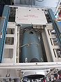
Open 565
-

-
RM565 with P7 CRT


