7000 series readout system: Difference between revisions
No edit summary |
|||
| (36 intermediate revisions by 7 users not shown) | |||
| Line 1: | Line 1: | ||
{{Instrument Sidebar | |||
|class=Subsystem | |||
|manufacturer=Tektronix | |||
|series= | |||
|model=7000-series readout system | |||
|summary= | |||
|image=Tek-7000-readout-board.jpg | |||
|caption=Classic 7000 series readout board (analog ROMs) | |||
|introduced=1969 | |||
|discontinued=1992 | |||
|designers=Barrie Gilbert | |||
|manuals= | |||
}} | |||
For the [[7000-series scopes]], a system was required to display the instrument state such as input range, time/div etc. alongside or within the display. Earlier solutions had included fiber-optical/mechanical displays to the side of the CRT such as those in the [[576|576 Curve Tracer]]. | For the [[7000-series scopes]], a system was required to display the instrument state such as input range, time/div etc. alongside or within the display. Earlier solutions had included fiber-optical/mechanical displays to the side of the CRT such as those in the [[576|576 Curve Tracer]]. | ||
The design ultimately selected for the 7000 series was proposed and designed by [[Barrie Gilbert]]. It uses the CRT beam to display annotations in the same focal plane as the scope's main display. | The design ultimately selected for the 7000 series was proposed and designed by [[Barrie Gilbert]]. It uses the CRT beam to display annotations in the same focal plane as the scope's main display. | ||
The same readout system was later used in the [[5440]] and [[5444]] scopes from the [[5000-series scopes | 5000 series]]. | |||
==Concept== | ==Concept== | ||
| Line 11: | Line 26: | ||
===Readout modes=== | ===Readout modes=== | ||
[[File:tek_readout_beam.jpg|thumb|right|200px|Signal beam interruption by readout seen on beam 2 of a [[7844]]]] | [[File:tek_readout_beam.jpg|thumb|right|200px|Signal beam interruption by readout seen on beam 2 of a [[7844]]]] | ||
The standard mode of operation for the readout is free-running, i.e. in regular intervals that are asynchronous to the sweep, beam control is switched to the readout generator. In certain conditions, this can cause visible gaps in the signal display. When the readout intensity control is turned to minimum, this switching is disabled and the signal trace is not interrupted at all. | The standard mode of operation for the readout is free-running, i.e. in regular intervals that are asynchronous to the sweep, beam control is switched to the readout generator. In certain conditions, this can cause visible gaps in the signal display. When the readout intensity control is turned to minimum, this switching is disabled and the signal trace is not interrupted at all. (In the [[7844]] with its two physically separate beams, readout uses beam 2, and beam 1 is never interrupted.) | ||
A sliding switch on the analog ROM readout board (internal to the scope) allows the operator to select "gate triggered" mode, in which the readout signal is produced only after a sweep has occurred. The advantage of this mode is that the beam is not interrupted while drawing the signal, however, if no sweep occurs there is no readout, and if the sweep is slow, the readout flickers. | A sliding switch on the analog ROM readout board (internal to the scope) allows the operator to select "gate triggered" mode, in which the readout signal is produced only after a sweep has occurred. The advantage of this mode is that the beam is not interrupted while drawing the signal, however, if no sweep occurs there is no readout, and if the sweep is slow, the readout flickers. | ||
In certain mainframes such as the [[7844]], [[7904A]] and [[7104]], turning the display intensity control past the maximum intensity setting switches readout into pulsed mode. | In certain mainframes such as the [[7844]], [[7904A]], [[7934]], and [[7104]], turning the readout display intensity control past the maximum intensity setting switches readout into pulsed mode. | ||
Depending on a second switch, readout occurs at the end of the sweep ("+ GATE") or when triggered by a back-panel "Graticule/Readout Single Shot" input. These scopes also have a "manual readout" button and similar controls for pulsed graticule illumination. | Depending on a second switch, readout occurs at the end of the sweep ("+ GATE") or when triggered by a back-panel "Graticule/Readout Single Shot" input. These scopes also have a "manual readout" button and similar controls for pulsed graticule illumination. | ||
===Scanning=== | ===Scanning=== | ||
The oscilloscope readout system produces a pulse train consisting of 10 successive negative-going pulses representing a possible character in a readout | The oscilloscope readout system produces a pulse train consisting of 10 successive negative-going pulses representing a possible character in a readout word. Each time-slot pulse is output at −15 V onto one of ten lines, labeled TS-1 through TS-10 (Time Slots 1 through 10), which are connected to the vertical and horizontal plug-in compartments. | ||
Two output lines, row and column, are connected from each channel (two channels per plug-in compartment) back to the oscilloscope readout system. Data is encoded on these output lines as a pair of analog current sequences in 100 μA steps from 0 to 0.9 mA for rows and 0 to 1.0 mA for columns, the combination of which can address a matrix of 11 × 10 positions. In this matrix, rows 1, 2, 4, 5 and 6 correspond to characters, whereas other rows are used to encode instructions: | |||
[[File:Tek7000-readout-charset.jpg|center|600px]] | [[File:Tek7000-readout-charset.jpg|center|600px]] | ||
In time slot 1, special operations can be requested that affect the display in later time slots. These commands are designed to simplify display changes required by external probes that request beam identification or change input sensitivity. The "Identify" command switches to an internal program displaying IDENTIFY instead of any encoded value. Command R3/C1 requests an additional zero to be added starting in time slot 5, R3/C2 adds two such zeroes, R3/C3 shifts the selected prefix one code to the left (i.e. | In time slot 1, special operations can be requested that affect the display in later time slots. These commands are designed to simplify display changes required by external probes that request beam identification or change input sensitivity. The "Identify" command switches to an internal program displaying the word "IDENTIFY" instead of any encoded value. Command R3/C1 requests an additional zero to be added starting in time slot 5, R3/C2 adds two such zeroes, R3/C3 shifts the selected prefix one code to the left (i.e. p → n, n → μ, μ → m, m → space), and R3/C4 shifts the prefix and adds a zero. (See the [[Media:Tek-plugin-readout.jpg|encoding circuit of the 7A18 plugin]] for an example implementation.) It is also possible to request a decimal point to be drawn without losing display digits, by encoding row 7 commands in time slot 1. | ||
Additionally, R13 (row 13, selected by a row current of 1.3 mA) will produce a jump command by turning Q2153 off. This advances the display to the next channel, i.e. skips all following time slots of the current channel and their display. | |||
Normally the readout will only display the channels of those plugins that are active as per the mode switches (P1018-P2118, channel inhibit), however individual plugins can override this by pulling the A35 ("override channel inhibit") line low. If the two channels of a plugin are inhibited, i.e. A35 is high, two diodes (e.g. CR2163 and CR2162, with current sharing resistors) inject current into the A38/A37 line, effectively deleting the readout data. | Normally the readout will only display the channels of those plugins that are active as per the mode switches (P1018-P2118, channel inhibit), however, individual plugins can override this by pulling the A35 ("override channel inhibit") line low. If the two channels of a plugin are inhibited, i.e. A35 is high at +15 V, two diodes (e.g. CR2163 and CR2162, with current sharing resistors) inject current into the A38/A37 line, effectively deleting the readout data by producing SKIP or space (C-0, R-x) instructions. | ||
===Plug-in circuit=== | ===Plug-in circuit=== | ||
| Line 33: | Line 51: | ||
A simple plug-in such as a vertical amplifier will only require a small number of resistors and possibly diodes in addition to a suitably coded switch. | A simple plug-in such as a vertical amplifier will only require a small number of resistors and possibly diodes in addition to a suitably coded switch. | ||
It will use TS1 to encode the number of zeros, TS2 to display a down-arrow indicating an inverted input, TS3 to display ">" or "<" if the input is uncalibrated, TS4 for a digit, TS8 for a unit prefix like "μ" and TS9 for a unit like "V". The other slots are unused | It will use TS1 to encode the number of zeros, TS2 to display a down-arrow indicating an inverted input, TS3 to display ">" or "<" if the input is uncalibrated, TS4 for a digit, TS8 for a unit prefix like "μ" and TS9 for a unit like "V". The other slots are unused (see illustration). | ||
===Probe interface=== | ===Probe interface=== | ||
Most 7000 series plugins have rings around the BNC input sockets that allow attached probes to interface with the readout system. The probe connector includes a contact pin connecting this ring. A resistor connected to ground encodes the probe attenuation, e.g. 11 kΩ indicates a ×10 probe and 6.8 kΩ a ×100 probe. If the probe includes an Identify switch at the tip, this connects the readout pin directly to ground.The [[Media:Tek-plugin-readout.jpg|plug-in circuit]] uses the shift instructions in time slot 1 to implement the change of range. | Most 7000 series plugins have [[BNC connector with readout ring|rings around the BNC input sockets]] that allow attached probes to interface with the readout system. The probe connector includes a contact pin connecting this ring. A resistor connected to ground encodes the probe attenuation, e.g. 11 kΩ indicates a ×10 probe and 6.8 kΩ a ×100 probe. If the probe includes an Identify switch at the tip, this connects the readout pin directly to ground. | ||
The [[Media:Tek-plugin-readout.jpg|plug-in circuit]] uses the shift instructions in time slot 1 to implement the change of range, which is done by adding 100 μA (1 step) to the column current in time slot 1 for a ×10 probe, or 200 μA (2 steps) for a ×100 probe. For example, if the encoded unit was 100 mV, TS4 would encode a "1" digit, TS-8 the "m" prefix, and TS-1 the "add two zeros" command (R3/C2). Connecting a ×10 probe adds 100 μA in TS1, selecting the "shift prefix left" command (R3/C3) instead of "add two zeros". This drops the extra zeros and changes the prefix "m" to none, thus the display changes to "1 V". With a ×100 probe, the command selected would be "shift prefix left and add one zero" (R3/C4) and the resulting display becomes "10 V". | |||
===Complex plugins=== | ===Complex plugins=== | ||
| Line 45: | Line 65: | ||
The [[067-0905-99]] "Readout Exerciser" is a test fixture for the readout system. | The [[067-0905-99]] "Readout Exerciser" is a test fixture for the readout system. | ||
==Implementation== | ==Implementation== | ||
| Line 52: | Line 71: | ||
====Character generation==== | ====Character generation==== | ||
[[File:7000-readout-chargen-positions.jpg|thumb|300px|right|Character generator matrix positions in 7000 series readout analog character generator ROM]] | [[File:7000-readout-chargen-positions.jpg|thumb|300px|right|Character generator matrix positions in 7000 series readout analog character generator ROM]] | ||
The character generators are custom analog chips that provide X and Y output currents for ten characters of up to seven strokes (eight X/Y coordinate pairs) inscribing each character. The in-character coordinate points are selected through a triangular analog signal, not a digital code, which in turn activates one of eight groups of three transistors each generating the X/Y output currents. Each of these groups is fed a constant emitter current (I<sub>E</sub>), and the distribution of this current to the three transistors is controlled by their different emitter areas. The first and second collectors provide X and Y currents respectively, the third ("Z") directs current to the substrate (I<sub>E</sub> - I<sub>X</sub> - I<sub>Y</sub> - I<sub>Z</sub> = 0). Actually, the emitter area itself is not varied in the mask, but out of a fixed number of emitters of equal size, a certain number is connected on each transistor | The character generators are custom analog chips that provide X and Y output currents for ten characters of up to seven strokes (eight X/Y coordinate pairs) inscribing each character. The in-character coordinate points are selected through a triangular analog character scan signal, not a digital code, which in turn activates one of eight groups of three transistors each generating the X/Y output currents. Each of these groups is fed a constant emitter current (I<sub>E</sub>), and the distribution of this current to the three transistors is controlled by their different emitter areas. The first and second collectors provide X and Y currents respectively, the third ("Z") directs current to the substrate (I<sub>E</sub> - I<sub>X</sub> - I<sub>Y</sub> - I<sub>Z</sub> = 0). Actually, the emitter area itself is not varied in the mask, but out of a fixed number of emitters of equal size, a certain number is connected on each transistor (see illustration). This allowed all character generator ICs to be manufactured with the same silicon layout, differing only in the metallization layers. [[File:7000-readout-chargen-circuit-1.jpg|300px|thumb|ROM circuit for one character (digit "3"). Bases are scanned in turn. The numbers under the emitters indicate how many of the emitters are connected to the common rail. Ten such character circuits plus the scanning (base drive) circuit are integrated in each ROM chip. All X and Y collector outputs are connected across characters and chips.]] | ||
If the bases were controlled by a digital decoder, only one triplet of transistors would be active at any time and only points would be generated on the display. Instead, through an analog driving circuit, gradual cut-over is achieved, i.e. current from one group is reduced while that from the next group is increased, and a linear transition from the first to the second X/Y coordinate pair is displayed as a stroke on the CRT. The actual shape of the base drive voltages has great influence on the proper character rendering (this is explained at length in Gilbert's 1971 SSC paper). | If the bases were controlled by a digital decoder, only one triplet of transistors would be active at any time and only points would be generated on the display. Instead, through an analog driving circuit, gradual cut-over is achieved, i.e. current from one group is reduced while that from the next group is increased, and a linear transition from the first to the second X/Y coordinate pair is displayed as a stroke on the CRT. The actual shape of the base drive voltages has great influence on the proper character rendering (this is explained at length in Gilbert's 1971 SSC paper). | ||
| Line 74: | Line 93: | ||
===7854=== | ===7854=== | ||
The [[7854]] contains a microprocessor controlled 40x16 character display generator which is also used to display plugin readout. The readout interface therefore contains only the column driver, multiplexer and A/D section but not the character generator - it only feeds readout data to the microprocessor. | The [[7854]] contains a microprocessor-controlled 40x16 character display generator which is also used to display plugin readout data. | ||
The readout interface therefore contains only the column driver, multiplexer and A/D section but not the character generator - it only feeds readout data to the microprocessor. | |||
===EPROM-based Readout Board=== | ===EPROM-based Readout Board=== | ||
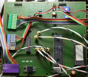
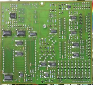
[[File:EPROM based 7000 series readout board.jpg|400px|right]] | [[File:EPROM based 7000 series readout board.jpg|400px|right]] | ||
Towards the end of the 7000 series lifespan, in the | Towards the end of the 7000 series lifespan, in the second half of the 1980s, a re-designed readout board (Tek part number 670-8622) | ||
Tek part number 670-8622 | was introduced, in which the character generator is based on digital values stored in a 2732 EPROM instead of Gilbert's analog ROMs, | ||
with the number of display points increased to up to 16 per character. | |||
This board was installed e.g. in the [[7934]], [[R7103]], and [[7904A]] and still used some of the Tek-made readout ICs like the timing generator. | |||
The design is similar to the readout mechanism in the [[2465]] series. | |||
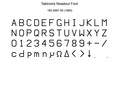
The presence of this board can be detected from the outside by looking at the readout characters which are straight up but were italicized | |||
in the analog version (which was done the analog way too, by adding some 10% of the vertical signal to the horizontal channel). | |||
The character style itself is also different — for example, the "V" in the classic board has just two straight lines, whereas they are angled in the digital version. | |||
:{| | :{| | ||
| Line 87: | Line 113: | ||
| [[File:Readout-1.jpg]] || [[File:Readout-2.jpg]] | | [[File:Readout-1.jpg]] || [[File:Readout-2.jpg]] | ||
|- | |- | ||
| Analog ROM board || EPROM board | | Analog ROM board || EPROM or μC board | ||
|- | |- | ||
|} | |} | ||
===Microcontroller-based Readout Board=== | ===Microcontroller-based Readout Board=== | ||
Finally, from 1989/1990 on, a third generation readout board designed around an 80C31 micro-controller replaced the previous versions in the last series of [[7104]], [[R7103]], [[R7844]] and [[ | Finally, from 1989/1990 on, a third generation readout board designed around an 80C31 micro-controller replaced the previous versions in the last series of [[7104]], [[R7103]], [[R7844]], [[7904A]], [[7603]] and [[7623B]] models. This version no longer used any Tek-made special ICs, manufacture of which had been discontinued by that time. The board is part SMD, part through-hole. | ||
It is described in | |||
[[Media:070-4593-00.pdf|this version of the 7904A manual]] | |||
(pages 288 through 291 describe the EPROM version above, while the 80C31 version is shown on pages 380 through 391). | |||
<gallery widths=300 heights=300> | |||
7000-readout-ctl-1.jpg | top of board | |||
7000-readout-ctl-2.jpg | bottom of board | |||
7000-readout-ctl-3.jpg | | |||
Microcontroller based readout board block diagram.jpg | Block diagram | |||
Late 7603 with digital readout.jpg | Late model [[7603]] with μP readout | |||
</gallery> | |||
==Literature== | ==Literature== | ||
* Barrie Gilbert, ''[ | * Barrie Gilbert, ''[https://ieeexplore.ieee.org/abstract/document/1050157 Monolithic Analog READ-ONLY Memory for Character Generation]'', IEEE J. of Solid-State Circuits, 1971. | ||
* [[Patent US 3651510A|US Patent 3,651,510, ''Character generator apparatus'']] | |||
==Links== | ==Links== | ||
* [http://www.amplifier.cd/Test_Equipment/Tektronix/Tektronix_7000_series_mainframe/rep-und-kal-7603/Reparaturbericht%20TEKTRONIX%207603.htm Repair of readout and installation of readout board in another scope] (many photos, German text) | * [http://www.amplifier.cd/Test_Equipment/Tektronix/Tektronix_7000_series_mainframe/rep-und-kal-7603/Reparaturbericht%20TEKTRONIX%207603.htm Repair of readout and installation of readout board in another scope] (many photos, German text) | ||
* [http://www.electronics-related.com/sci.electronics.design/thread/116046/readout-pin-on-oscilloscope-probes.php Thread about probe readout details] | * [http://www.electronics-related.com/sci.electronics.design/thread/116046/readout-pin-on-oscilloscope-probes.php Thread about probe readout details] | ||
* [[Media:7000 series scale factor readout.pdf|Tektronix 7000 Series Scale Factor Readout (PDF, OCR)]] | |||
* [[7000 Series plug-in interface]] | |||
==Character code table== | ==Character code table== | ||
| Line 156: | Line 194: | ||
</div> | </div> | ||
==Font comparison== | |||
<gallery> | |||
Font_160-2997-00.pdf|Font of the 1984 EPROM readout | |||
Font_160-2997-01.pdf|Font of the 1986 EPROM readout | |||
Font_160-2997-xx.pdf|Font comparison 1984 vs 1986 EPROM readout | |||
</gallery> | |||
{{Custom ICs|7000 series readout system}} | |||
[[Category:7000 series scopes]] | [[Category:7000 series scopes]] | ||
Latest revision as of 06:44, 9 December 2023
For the 7000-series scopes, a system was required to display the instrument state such as input range, time/div etc. alongside or within the display. Earlier solutions had included fiber-optical/mechanical displays to the side of the CRT such as those in the 576 Curve Tracer.
The design ultimately selected for the 7000 series was proposed and designed by Barrie Gilbert. It uses the CRT beam to display annotations in the same focal plane as the scope's main display.
The same readout system was later used in the 5440 and 5444 scopes from the 5000 series.
Concept
Layout

A total of eight display fields can be superimposed on the CRT picture, four on top and four at the bottom. These are logically associated with the four possible slots in full-size mainframes, with the top field corresponding to the first channel, primary time base or primary function of a plug-in, and the bottom field corresponding to a second channel, delayed timebase, secondary function or unit label.
Readout modes

The standard mode of operation for the readout is free-running, i.e. in regular intervals that are asynchronous to the sweep, beam control is switched to the readout generator. In certain conditions, this can cause visible gaps in the signal display. When the readout intensity control is turned to minimum, this switching is disabled and the signal trace is not interrupted at all. (In the 7844 with its two physically separate beams, readout uses beam 2, and beam 1 is never interrupted.)
A sliding switch on the analog ROM readout board (internal to the scope) allows the operator to select "gate triggered" mode, in which the readout signal is produced only after a sweep has occurred. The advantage of this mode is that the beam is not interrupted while drawing the signal, however, if no sweep occurs there is no readout, and if the sweep is slow, the readout flickers.
In certain mainframes such as the 7844, 7904A, 7934, and 7104, turning the readout display intensity control past the maximum intensity setting switches readout into pulsed mode. Depending on a second switch, readout occurs at the end of the sweep ("+ GATE") or when triggered by a back-panel "Graticule/Readout Single Shot" input. These scopes also have a "manual readout" button and similar controls for pulsed graticule illumination.
Scanning
The oscilloscope readout system produces a pulse train consisting of 10 successive negative-going pulses representing a possible character in a readout word. Each time-slot pulse is output at −15 V onto one of ten lines, labeled TS-1 through TS-10 (Time Slots 1 through 10), which are connected to the vertical and horizontal plug-in compartments.
Two output lines, row and column, are connected from each channel (two channels per plug-in compartment) back to the oscilloscope readout system. Data is encoded on these output lines as a pair of analog current sequences in 100 μA steps from 0 to 0.9 mA for rows and 0 to 1.0 mA for columns, the combination of which can address a matrix of 11 × 10 positions. In this matrix, rows 1, 2, 4, 5 and 6 correspond to characters, whereas other rows are used to encode instructions:

In time slot 1, special operations can be requested that affect the display in later time slots. These commands are designed to simplify display changes required by external probes that request beam identification or change input sensitivity. The "Identify" command switches to an internal program displaying the word "IDENTIFY" instead of any encoded value. Command R3/C1 requests an additional zero to be added starting in time slot 5, R3/C2 adds two such zeroes, R3/C3 shifts the selected prefix one code to the left (i.e. p → n, n → μ, μ → m, m → space), and R3/C4 shifts the prefix and adds a zero. (See the encoding circuit of the 7A18 plugin for an example implementation.) It is also possible to request a decimal point to be drawn without losing display digits, by encoding row 7 commands in time slot 1.
Additionally, R13 (row 13, selected by a row current of 1.3 mA) will produce a jump command by turning Q2153 off. This advances the display to the next channel, i.e. skips all following time slots of the current channel and their display.
Normally the readout will only display the channels of those plugins that are active as per the mode switches (P1018-P2118, channel inhibit), however, individual plugins can override this by pulling the A35 ("override channel inhibit") line low. If the two channels of a plugin are inhibited, i.e. A35 is high at +15 V, two diodes (e.g. CR2163 and CR2162, with current sharing resistors) inject current into the A38/A37 line, effectively deleting the readout data by producing SKIP or space (C-0, R-x) instructions.
Plug-in circuit

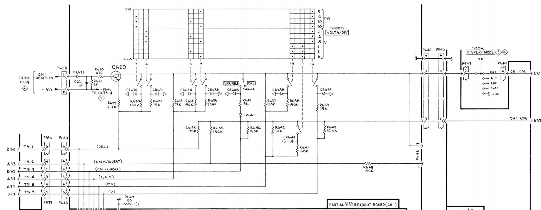
A plug-in encodes the desired read-out information either by connecting resistors between the output lines and the time-slot input lines, or by generating equivalent currents.
A simple plug-in such as a vertical amplifier will only require a small number of resistors and possibly diodes in addition to a suitably coded switch. It will use TS1 to encode the number of zeros, TS2 to display a down-arrow indicating an inverted input, TS3 to display ">" or "<" if the input is uncalibrated, TS4 for a digit, TS8 for a unit prefix like "μ" and TS9 for a unit like "V". The other slots are unused (see illustration).
Probe interface
Most 7000 series plugins have rings around the BNC input sockets that allow attached probes to interface with the readout system. The probe connector includes a contact pin connecting this ring. A resistor connected to ground encodes the probe attenuation, e.g. 11 kΩ indicates a ×10 probe and 6.8 kΩ a ×100 probe. If the probe includes an Identify switch at the tip, this connects the readout pin directly to ground.
The plug-in circuit uses the shift instructions in time slot 1 to implement the change of range, which is done by adding 100 μA (1 step) to the column current in time slot 1 for a ×10 probe, or 200 μA (2 steps) for a ×100 probe. For example, if the encoded unit was 100 mV, TS4 would encode a "1" digit, TS-8 the "m" prefix, and TS-1 the "add two zeros" command (R3/C2). Connecting a ×10 probe adds 100 μA in TS1, selecting the "shift prefix left" command (R3/C3) instead of "add two zeros". This drops the extra zeros and changes the prefix "m" to none, thus the display changes to "1 V". With a ×100 probe, the command selected would be "shift prefix left and add one zero" (R3/C4) and the resulting display becomes "10 V".
Complex plugins
The 7M13 plugin allows the user to encode arbitrary text and numbers plus an optional picture counter value, for photographic documentation.
Digital delay or counter plugins like the 7D11 or 7D14 display up to 8 digit counts in the top field and a unit (e.g. MHz) in the bottom field.
The 067-0905-99 "Readout Exerciser" is a test fixture for the readout system.
Implementation
Analog-ROM Readout Board
Character generation

The character generators are custom analog chips that provide X and Y output currents for ten characters of up to seven strokes (eight X/Y coordinate pairs) inscribing each character. The in-character coordinate points are selected through a triangular analog character scan signal, not a digital code, which in turn activates one of eight groups of three transistors each generating the X/Y output currents. Each of these groups is fed a constant emitter current (IE), and the distribution of this current to the three transistors is controlled by their different emitter areas. The first and second collectors provide X and Y currents respectively, the third ("Z") directs current to the substrate (IE - IX - IY - IZ = 0). Actually, the emitter area itself is not varied in the mask, but out of a fixed number of emitters of equal size, a certain number is connected on each transistor (see illustration). This allowed all character generator ICs to be manufactured with the same silicon layout, differing only in the metallization layers.

If the bases were controlled by a digital decoder, only one triplet of transistors would be active at any time and only points would be generated on the display. Instead, through an analog driving circuit, gradual cut-over is achieved, i.e. current from one group is reduced while that from the next group is increased, and a linear transition from the first to the second X/Y coordinate pair is displayed as a stroke on the CRT. The actual shape of the base drive voltages has great influence on the proper character rendering (this is explained at length in Gilbert's 1971 SSC paper).

Custom chips

- 155-0014-01 Analog to Decimal Converter
- 155-0015-01 Analog Data Switch
- 155-0017-00 Zero Logic Counter
- 155-0018-00 Zeros Logic
- 155-0019-00 Decimal Point and Spacing
- 155-0020-00 Output Assembler
- 155-0021-00 Timing Generator
- 155-0023-00 R-1 Character generator (Numerals 0 1 2 3 4 5 6 7 8 9)
- 155-0024-00 R-2 Character generator (Special Symbols ↓ < I / + - + C Δ >)
- 155-0025-00 R-4 Character generator (Prefixes m μ n p X K M G T R)
- 155-0026-00 R-5 Character generator (Letters S V A W H d B c Ω E)
- 155-0027-00 R-6 Character generator (Special Alpha U N L Z Y P F J Q D)
- 155-0038-01 D/A converter
7854
The 7854 contains a microprocessor-controlled 40x16 character display generator which is also used to display plugin readout data. The readout interface therefore contains only the column driver, multiplexer and A/D section but not the character generator - it only feeds readout data to the microprocessor.
EPROM-based Readout Board

Towards the end of the 7000 series lifespan, in the second half of the 1980s, a re-designed readout board (Tek part number 670-8622) was introduced, in which the character generator is based on digital values stored in a 2732 EPROM instead of Gilbert's analog ROMs, with the number of display points increased to up to 16 per character.
This board was installed e.g. in the 7934, R7103, and 7904A and still used some of the Tek-made readout ICs like the timing generator. The design is similar to the readout mechanism in the 2465 series.
The presence of this board can be detected from the outside by looking at the readout characters which are straight up but were italicized in the analog version (which was done the analog way too, by adding some 10% of the vertical signal to the horizontal channel). The character style itself is also different — for example, the "V" in the classic board has just two straight lines, whereas they are angled in the digital version.


Analog ROM board EPROM or μC board


Microcontroller-based Readout Board
Finally, from 1989/1990 on, a third generation readout board designed around an 80C31 micro-controller replaced the previous versions in the last series of 7104, R7103, R7844, 7904A, 7603 and 7623B models. This version no longer used any Tek-made special ICs, manufacture of which had been discontinued by that time. The board is part SMD, part through-hole. It is described in this version of the 7904A manual (pages 288 through 291 describe the EPROM version above, while the 80C31 version is shown on pages 380 through 391).
-
top of board
-
bottom of board
-

-

Block diagram
-
Late model 7603 with μP readout


Literature
- Barrie Gilbert, Monolithic Analog READ-ONLY Memory for Character Generation, IEEE J. of Solid-State Circuits, 1971.
- US Patent 3,651,510, Character generator apparatus
Links
- Repair of readout and installation of readout board in another scope (many photos, German text)
- Thread about probe readout details
- Tektronix 7000 Series Scale Factor Readout (PDF, OCR)
- 7000 Series plug-in interface
Character code table
- A R5/C3
- B R5/C7
- C R2/C8
- D R6/C10
- E R5/C10
- F R6/C7
- G R4/C8
- H R5/C5
- I R2/C3
- J R6/C8
- K R4/C6
- L R6/C3
- M R4/C7
- N R6/C2
- P R6/C6
- Q R6/C9
- R R4/C10
- S R5/C1
- T R4/C9
- U R6/C1
- V R5/C2
- W R5/C4
- X R4/C5
- Y R6/C5
- Z R6/C4
- m R4/C1
- μ R4/C2
- n R4/C3
- p R4/C4
- d R5/C6
- c R5/C8
- 0 R1/C1
- 1 R1/C2
- 2 R1/C3
- 3 R1/C4
- 4 R1/C5
- 5 R1/C6
- 6 R1/C7
- 7 R1/C8
- 8 R1/C9
- 9 R1/C10
- ↓ R2/C1
- < R2/C2
- / R2/C4
- > R2/C10
- Δ R2/C9
- + R2/C5 or R2/C7
- – R2/C6
- Ω R5/C9
Font comparison
-
Font of the 1984 EPROM readout
-
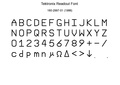
Font of the 1986 EPROM readout
-
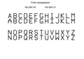
Font comparison 1984 vs 1986 EPROM readout


