7S11: Difference between revisions
No edit summary |
m (clean up, replaced: {{Plugin Sidebar 2| → {{Plugin Sidebar |, title=Tektronix → manufacturer=Tektronix | type=, series=7000-series scopes| → series=7000-series scopes|) |
||
| Line 1: | Line 1: | ||
{{Plugin Sidebar | {{Plugin Sidebar | | ||
manufacturer=Tektronix | type=7S11 | | |||
summary=Sampling plugin| | summary=Sampling plugin| | ||
image=7s11-s4.jpg | | image=7s11-s4.jpg | | ||
| Line 6: | Line 6: | ||
introduced=1969 | | introduced=1969 | | ||
discontinued=1990 | | discontinued=1990 | | ||
series= | series=7000-series scopes| | ||
manuals= | manuals= | ||
* [[Media:070-0985-00.pdf|Tektronix 7S11 Manual]] (OCR, PDF) | * [[Media:070-0985-00.pdf|Tektronix 7S11 Manual]] (OCR, PDF) | ||
| Line 12: | Line 12: | ||
}} | }} | ||
The '''Tektronix 7S11''' is a [[ | The '''Tektronix 7S11''' is a [[sampling oscilloscope|sampling]] plug-in for [[7000-series scopes]]. | ||
It takes one [[:7000 and 3S series sampling heads|S-series sampling head]], e.g. [[S-4]] or [[S-6]], | It takes one [[:7000 and 3S series sampling heads|S-series sampling head]], e.g. [[S-4]] or [[S-6]], | ||
| Line 40: | Line 40: | ||
==Links== | ==Links== | ||
* [[Media:Tekscope 1970 V2 N1 Feb 1970.pdf | Tekscope Vol. 2 No. 1, Feb 1970]] | * [[Media:Tekscope 1970 V2 N1 Feb 1970.pdf|Tekscope Vol. 2 No. 1, Feb 1970]] | ||
* [http://www.amplifier.cd/Test_Equipment/Tektronix/Tektronix_7000_series_special/7S11.htm Tektronix 7S11 @ amplifier.cd] | * [http://www.amplifier.cd/Test_Equipment/Tektronix/Tektronix_7000_series_special/7S11.htm Tektronix 7S11 @ amplifier.cd] | ||
* [http://www.barrytech.com/tektronix/tek7000/tek7s11.html Tektronix 7S11 @ barrytech.com] | * [http://www.barrytech.com/tektronix/tek7000/tek7s11.html Tektronix 7S11 @ barrytech.com] | ||
| Line 61: | Line 61: | ||
<gallery> | <gallery> | ||
7s11-1ghz-norm.jpg | 7S11, [[7T11]], [[S-4]] displaying a | 7s11-1ghz-norm.jpg | 7S11, [[7T11]], [[S-4]] displaying a 1 GHz sine (normal mode) | ||
7s11-1ghz-smooth.jpg | 7S11, [[7T11]], [[S-4]] displaying a | 7s11-1ghz-smooth.jpg | 7S11, [[7T11]], [[S-4]] displaying a 1 GHz sine (smooth mode) | ||
7s11-1ghz-smooth-store.jpg | 7S11, [[7T11]], [[S-4]] displaying a | 7s11-1ghz-smooth-store.jpg | 7S11, [[7T11]], [[S-4]] displaying a 1 GHz sine (smooth mode, variable-persistence storage display of a [[7613]] mainframe) | ||
7s12-7s11-1ghz-store.jpg | 7S11 used as 2nd channel with [[7S12]] | 7s12-7s11-1ghz-store.jpg | 7S11 used as 2nd channel with [[7S12]] | ||
Tek 7633 7s11 7t11.jpg|Rackmount [[7633]] with two 7S11 and a [[7T11]] displaying a | Tek 7633 7s11 7t11.jpg|Rackmount [[7633]] with two 7S11 and a [[7T11]] displaying a 2 GHz sinewave | ||
Adf4351 4GHz 7s11 7t11a.jpg|[[7704A]] with 7S11 and 7T11A displaying 4 GHz sizewave | Adf4351 4GHz 7s11 7t11a.jpg|[[7704A]] with 7S11 and 7T11A displaying 4 GHz sizewave | ||
</gallery> | </gallery> | ||
Revision as of 03:36, 9 August 2021

The Tektronix 7S11 is a sampling plug-in for 7000-series scopes.
It takes one S-series sampling head, e.g. S-4 or S-6, to form a complete vertical plug-in. Bandwidth and sensitivity are determined by the sampling head, not the plug-in.
For operation, a 7T11 or 7S12 plug-in is needed, to which the 7S11 connects through contact strips on the right side of the plug-in. The control signals are routed to a similar strip on the left of the module for another 7S11 in a dual-channel configuration. An alternative configuration consists of a pair of 7S11s, one in the right vertical and the other in the A or only horizontal bay, for an X-Y display in free-running mode.
The dc offset voltage as well as the vertical display signal are accessible on the front panel through Pin Tip jacks.
Key Specifications
| Deflection factor | 2 to 200 in 1−2−5 sequence, unit as labelled on the sampling head (usually mV, except for the optical-input S-42 scaled in mW) |
|---|---|
| DC Offset range | ±1 V |
| Offset output | 10 × offset voltage (±10 V), source impedance 10 kΩ, 2 mm Pin Tip connector |
| Vertical signal output | 200 mV/Div, max. 2.4 Vp-p, source impedance 10 kΩ, 2 mm Pin Tip connector |
| Delay range | at least 10 ns |
| Weight | 0.9 kg (3.25 lbs) |
Internals
The 7S11 does not contain integrated circuits (except dual transistors).
Links
Pictures
-
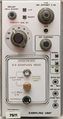
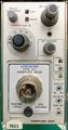
7S11 with inserted S-4 head
-
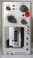
7S11 with empty plugin bay
-
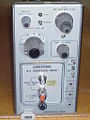
7S11 with inserted S-6 sampling head
-
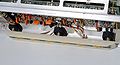
spring-loaded contact block (right)
-
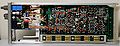
right side, cover removed
-
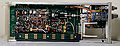
left side, cover removed
-
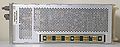
right side
-
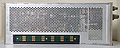
left side
-
7S11 with S-1


