FG502: Difference between revisions
No edit summary |
No edit summary |
||
| Line 43: | Line 43: | ||
* (Tantalum) Electolytic capacitors, especially on the output transistors. | * (Tantalum) Electolytic capacitors, especially on the output transistors. | ||
* [https://www.amplifier.cd/Test_Equipment/Tektronix/Tektronix_500/Reparatur%20Tektronix%20FG502-1-com.pdf FG502 repair report @ amplifier.cd] (German) | * [https://www.amplifier.cd/Test_Equipment/Tektronix/Tektronix_500/Reparatur%20Tektronix%20FG502-1-com.pdf FG502 repair report @ amplifier.cd] (German) | ||
* [[Media:Repair FG502 English.pdf|FG502 repair report @ amplifier. | * [[Media:Repair FG502 English.pdf|FG502 repair report @ amplifier.cd (English Translation)]] | ||
* [https://www.electronicdesign.com/technologies/test-measurement/article/21137778/the-tektronix-function-generator-teardown The Tektronix Function Generator Teardown] - Paul Rako @ electronicdesign.com | * [https://www.electronicdesign.com/technologies/test-measurement/article/21137778/the-tektronix-function-generator-teardown The Tektronix Function Generator Teardown] - Paul Rako @ electronicdesign.com | ||
* For serial numbers below B050740, some FG502's may not shift Output Frequency 1000:1 with 10 V or less as specified. To correct this problem, change R125 from 10 kΩ to 9.41 kΩ. | * For serial numbers below B050740, some FG502's may not shift Output Frequency 1000:1 with 10 V or less as specified. To correct this problem, change R125 from 10 kΩ to 9.41 kΩ. | ||
Revision as of 11:12, 22 September 2022

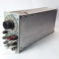
The Tektronix FG502 is a function generator plug-in for the TM500 system.
It generates low distortion sine, square, triangle, positive and negative pulse, and ramp waveforms from 0.1 Hz to 11 MHz.
A squarewave trigger is available at the front panel. Variable DC offset is also provided.
Α voltage-controlled frequency (VCF) input controls the output frequency from an external voltage source. The output frequency can be swept above or below the selected frequency to maximum of 1000:1 depending on the polarity and amplitude of the VCF input and the selected output frequency.
An external gate input allows the generator to operate for the duration of an externally applied gating signal. This mode provides either a single cycle output, or a train of preselected waveforms, depending on the gating signal width and the generator frequency setting.
Key Specifications
| Frequency | 0.1 Hz to 11 MHz, resolution 10-4 |
|---|---|
| Frequency stability | ≤0.1% for 1 hour, ≤0.5% for 24 hours (ambient +25 °C ±5 °C) |
| Frequency accuracy | <3% of full scale from 0.1 Hz to 1 MHz. <5% of full scale from 1 MHz to 10 MHz |
| Output Amplitude | >10 Vp-p open circuit. >5 Vp-p into 50 Ω (@ 10 kHz) |
| Output Offset | >±5 Vp-p open circuit. >±2.5 Vp-p into 50 Ω |
| Amplitude flatness | Sine, ±1.5 dB ref. to 10 kHz; Square, triangle ±3 dB referenced to sine |
| Sine Distortion | < 0.5% from 10 Hz to 50 kHz. Harmonics >30 dB down at all other frequencies |
| Triangle Symmetry and Linearity | Within 1% from 0.1 Hz to 1.1 MHz, 3% from 1.1 MHz to 11 MHz |
| Risetime (Square/Pulse) | <20 ns |
| VCF | 10 V signal shifts frequency >1000:1 |
| Ext. Gate | 0 to >+2 V, not to exceed +15 V |
| Trigger Output | >5 V open circuit, >2.5 V into 50 Ω |
| Functions | Sine, Square, Triangle, + and − Ramp, + and − Pulse |
Rear Interface
- Output: A28 (GND A27)
- Trigger Output: B27 (GND B28)
- Gate In: B24 (GND B25)
- VCF In: B21 (GND B22)
Repair Issues
- Helitrim potentiometers are prone to failure due to cracking plastic axle.
- (Tantalum) Electolytic capacitors, especially on the output transistors.
- FG502 repair report @ amplifier.cd (German)
- FG502 repair report @ amplifier.cd (English Translation)
- The Tektronix Function Generator Teardown - Paul Rako @ electronicdesign.com
- For serial numbers below B050740, some FG502's may not shift Output Frequency 1000:1 with 10 V or less as specified. To correct this problem, change R125 from 10 kΩ to 9.41 kΩ.
Pictures
-

-
-

-

-
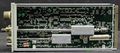
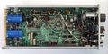
right internal view
-
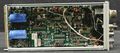
left internal view
-
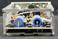
rear view
-
-

-
-

-
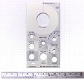
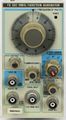
front plate


