S: Difference between revisions
No edit summary |
No edit summary |
||
| (10 intermediate revisions by 4 users not shown) | |||
| Line 1: | Line 1: | ||
{{Plugin Sidebar | {{Plugin Sidebar | ||
|manufacturer=Tektronix | |||
summary=Diode recovery tester plug-in| | |series=500-series scopes | ||
image= | |type=Type S | ||
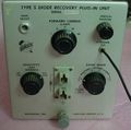
caption=Type S front view| | |summary=Diode recovery tester plug-in | ||
introduced=1960 | | |image=Tek_Type_S_Front–Tight.jpg | ||
discontinued=1967 | | |caption=Type S front view | ||
|introduced=1960 | |||
manuals= | |discontinued=1967 | ||
* [ | |designers= | ||
* [ | |manuals= | ||
* [[Media:070-223.pdf|Tektronix Type S Instruction Manual]] (OCR) | |||
* [[Media:tek_type_s_fcp.pdf|Tektronix Type S factory calibration procedure]] (OCR) | |||
}} | }} | ||
The '''Tektronix Type S''' is a plug-in for measuring semiconductor diode recovery characteristics. | The '''Tektronix Type S''' is a [[500-series scopes|500-series]] plug-in for measuring semiconductor diode recovery characteristics. | ||
It can be thought of as having two parts | It can be thought of as having two parts, a stimulus subsystem and a measurement subsystem. | ||
a stimulus subsystem and a measurement subsystem. | |||
The stimulus comes from [[mercury switch]] that drives a [[ECC86|6GM8/ECC86]] tube that operates in a current-steering mode. | The stimulus comes from [[mercury switch]] that drives a [[ECC86|6GM8/ECC86]] tube that operates in a current-steering mode. | ||
The measurement subsystem is a wideband amplifier that converts the single-ended voltage on the diode under test to the | The measurement subsystem is a wideband amplifier that converts the single-ended voltage on the diode under test to the differential signal that the oscilloscope mainframe takes. | ||
differential signal that the oscilloscope mainframe takes. | |||
One terminal of the diode is grounded. | One terminal of the diode is grounded. | ||
Measurements with the Type S are typically made by applying a current step to the diode while | Measurements with the Type S are typically made by applying a current step to the diode while observing the voltage across the diode. | ||
observing the voltage across the diode. | |||
The Type S was [[introduced in 1960]] and produced through 1966. | The Type S was [[introduced in 1960]] and produced through 1966. | ||
{{BeginSpecs}} | |||
{{Spec|Current ranges | Forward – 1, 2, 5, 10, and 20 mA; Reverse – 0, 0.1, 0.2, 0.5, 1.0, and 2.0 mA }} | |||
{{Spec|Vertical Deflection | 50 or 500 mV/div }} | |||
{{Spec|Shunt Capacitance | ~16 pF at 50 mV/div, ~9 pF at 500 mV/div }} | |||
{{Spec|Rise time | 1 ns }} | |||
{{EndSpecs}} | |||
==Pictures== | ==Pictures== | ||
<gallery> | <gallery> | ||
Tek_Type_S_Front.jpg | |||
Tek_Type_S_Right.jpg | |||
Tek_Type_S_Left.jpg | |||
Tek_Type_S_Top.jpg | |||
Tek_Type_S_Bottom.jpg | |||
Tek s schem b.png | Tek s schem b.png | ||
Tek_type_s.jpg|Front | Tek_type_s.jpg|Front | ||
| Line 36: | Line 43: | ||
S_3.JPG|Chassis bottom | S_3.JPG|Chassis bottom | ||
S_4.JPG|Mercury switch | S_4.JPG|Mercury switch | ||
Tek type s front2.jpeg | |||
</gallery> | </gallery> | ||
==Components== | |||
{{Parts|S}} | |||
[[Category:500 series plugins]] | [[Category:500 series plugins]] | ||
[[Category:Diode testers]] | |||
Latest revision as of 08:23, 6 December 2023

The Tektronix Type S is a 500-series plug-in for measuring semiconductor diode recovery characteristics.
It can be thought of as having two parts, a stimulus subsystem and a measurement subsystem. The stimulus comes from mercury switch that drives a 6GM8/ECC86 tube that operates in a current-steering mode. The measurement subsystem is a wideband amplifier that converts the single-ended voltage on the diode under test to the differential signal that the oscilloscope mainframe takes. One terminal of the diode is grounded.
Measurements with the Type S are typically made by applying a current step to the diode while observing the voltage across the diode.
The Type S was introduced in 1960 and produced through 1966.
Key Specifications
| Current ranges | Forward – 1, 2, 5, 10, and 20 mA; Reverse – 0, 0.1, 0.2, 0.5, 1.0, and 2.0 mA |
|---|---|
| Vertical Deflection | 50 or 500 mV/div |
| Shunt Capacitance | ~16 pF at 50 mV/div, ~9 pF at 500 mV/div |
| Rise time | 1 ns |
Pictures
-

-

-

-

-

-

-
Front
-
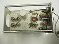
Chassis
-

Chassis bottom
-
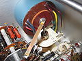
Mercury switch
-


Components
Some Parts Used in the S
| Part | Part Number(s) | Class | Description | Used in |
|---|---|---|---|---|
| 12AT7 | 154-0039-00 | Vacuum Tube (Dual Triode) | dual high-gain triode | 161 • 180 • 310 • 310A • 315 • 316 • 360 • 502 • 502A • 511A • 512 • 513 • 513D • 514 • 514AD • 514D • 516 • 524 • 529 • RM529 • 544 • 546 • 547 • 556 • 565 • 570 • 3A2 • 75 • 3A75 • 1M1 • A • B • C • G • H • K • L • ML • M • N • K • R • S • Z |
| 12AU6 | 154-0040-00 | Vacuum Tube (Pentode) | RF pentode | 81 • 112 • 1L10 • 1L20 • 1L60 • 3L10 • 512 • 556 • 575 • 545 • 547 • 549 • 581 • 585 • A • B • C • G • K • H • L • ML • M • N • O • R • S • Z |
| 6AK5 | 154-0014-00 • 154-0206-00 • 154-0084-00 | Vacuum Tube (Pentode) | RF pentode | B • C • CA • G • K • L • ML • S • Z • 517 • 517A • 524 |
| 6GM8 | 154-259 • 154-0259-00 | Vacuum Tube (Dual Triode) | dual triode | 81 • 516 • S |