Selenium rectifiers: Difference between revisions
Jump to navigation
Jump to search
(Added 180A to the list.) |
(Pic) |
||
| Line 11: | Line 11: | ||
* [http://w140.com/radios_master_1953_selenium_rectifiers.pdf Selenium Rectifier Section of 1953 Radio's Master Catalog (PDF)] | * [http://w140.com/radios_master_1953_selenium_rectifiers.pdf Selenium Rectifier Section of 1953 Radio's Master Catalog (PDF)] | ||
<gallery> | |||
Tek_180A-selenium-rect.jpg | Selenium rectifiers inside [[180A]] | |||
</gallery> | |||
[[Category:Semiconductor components]] | [[Category:Semiconductor components]] | ||
[[Category:Repair issues]] | [[Category:Repair issues]] | ||
Latest revision as of 12:07, 19 April 2020
Some classic Tek gear uses selenium rectifiers. It is recommended that these be replaced with modern silicon rectifiers. A problem however is that the original circuits were designed based in the voltage drop expected across a selenium rectifier, which is much more than the voltage drop across a silicon rectifier, therefore simply replacing the selenium part with a silicon part can result in an overvoltage situation. There are many solutions to this.
- One approach is to add a "dropping resistor" in series with a silicon rectifier. The resistance is selected to have a voltage drop that that compensates for the change in rectifiers.
- Another approach is to use several silicon rectifiers in series.
- Another approach is to wire transformers so that their secondaries partially buck the supply, thereby feeding less voltage to the silicon rectifiers so their output matches the voltage in the original design.
Selenium rectifiers are used in the P, 108, 127, 128, 180A, 310, 310A, 316, 317 507, 513, 515, 535, 545, and 575
-
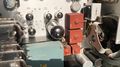
Selenium rectifiers inside 180A
