TM501: Difference between revisions
Jump to navigation
Jump to search
No edit summary |
No edit summary |
||
| (17 intermediate revisions by 5 users not shown) | |||
| Line 1: | Line 1: | ||
{{TM500 mainframe | |||
|mfg=Tektronix | |||
|type=TM501 | |||
|function=single-bay mainframe | |||
|image=Tek-tm501.jpg | |||
|introduced=1972 | |||
|discontinued=1991 | |||
|designers=Gunther Engert;Roger Stenbock; | |||
|manuals= | |||
* [[Media:070-1304-00.pdf|TM501 Manual 070-1304-00]] | |||
* [[Media:070-1304-01.pdf|TM501 Manual 070-1304-01]] | |||
}} | |||
On the '''TM501A''', the power switch has been moved to the rear. | |||
{{BeginSpecs}} | |||
{{Spec | Line Voltage | 100 V to 120 V / 108 V to 132 V}} | |||
{{Spec | Line Frequency | 40 Hz to 440 Hz }} | |||
{{Spec | Max Power | 120 W }} | |||
{{Spec | Weight | 2.3 kg (6 lbs) }} | |||
{{Spec | Size | 15.2 cm × 9.9 cm × 38.9 cm (H×W×L) (6.0" × 3.9" × 15.3") }} | |||
{{Spec | Plugin Supply | | |||
* +33.5 V / −33.5 V, 350 mA max ea. | |||
* +11.5 V, 1.3 A max | |||
* 17.5 V<sub>AC</sub> with grounded center tap, 30 VA max | |||
* 2 × 25 V<sub>AC</sub>, 2 x 0.5 A / 25 VA (combined) max; floating ≤350 V (peak) | |||
}} | |||
{{EndSpecs}} | |||
== | ===Options=== | ||
Option 2 adds internal pin headers for the slot as well as a rear 50-pin and BNC connector, allowing for custom wiring to and from the plugin. | |||
== | On the standard TM501, cutouts for the 50-pin and BNC socket have been made in the rear frame, meaning that the user only needs to drill holes in the rear cover plate to install the sockets. | ||
[[ | |||
==Links== | |||
* [https://www.youtube.com/watch?v=3qgTpMnht8I Tektronix TM501 Mainframe Restoration] by NFM @ YouTube | |||
* [[Media:TM501_Insulator_Plate_gerbers.zip|TM501 Insulator Plate - Gerber files]] (ZIP) (See TM501 restoration link above) | |||
{{Documents|Link=TM501}} | |||
{{Documents|Link=TM501A}} | |||
==Pictures== | ==Pictures== | ||
'''TM501''' | |||
<gallery> | <gallery> | ||
Tek-tm501.jpg | Front | |||
Tek tm501 1.jpg | Front | |||
Tek tm501 2.jpg | 3/4 View | |||
Tek tm501 3.jpg | Top | |||
Tek tm501 4.jpg | Rear | |||
Tek tm501 5.jpg | Rear | |||
Tek tm501 6.jpg | Internal | |||
Tek_TM501_Opt02.jpg | Option 02 | |||
</gallery> | |||
'''TM501A''' | |||
</gallery> | |||
Tek_TM501A_Front.jpg| Front | |||
Tek_TM501A_Rear.jpg | Rear | |||
</gallery> | </gallery> | ||
Latest revision as of 05:41, 19 February 2024

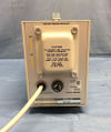
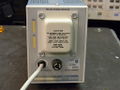
The Tektronix TM501 is a single-bay mainframe for the TM500 system. On the TM501A, the power switch has been moved to the rear.
Key Specifications
| Line Voltage | 100 V to 120 V / 108 V to 132 V |
|---|---|
| Line Frequency | 40 Hz to 440 Hz |
| Max Power | 120 W |
| Weight | 2.3 kg (6 lbs) |
| Size | 15.2 cm × 9.9 cm × 38.9 cm (H×W×L) (6.0" × 3.9" × 15.3") |
| Plugin Supply |
|
Options
Option 2 adds internal pin headers for the slot as well as a rear 50-pin and BNC connector, allowing for custom wiring to and from the plugin.
On the standard TM501, cutouts for the 50-pin and BNC socket have been made in the rear frame, meaning that the user only needs to drill holes in the rear cover plate to install the sockets.
Links
- Tektronix TM501 Mainframe Restoration by NFM @ YouTube
- TM501 Insulator Plate - Gerber files (ZIP) (See TM501 restoration link above)
Documents Referencing TM501
| Document | Class | Title | Authors | Year | Links |
|---|---|---|---|---|---|
| Tekscope 1972 V4 N3 May 1972.pdf | Article | TM500 series - A New Dimension in Plug-in Instrumentation | Bob Ragsdale | 1972 | TM500 system • TM501 • TM503 • FG501 • FG502 • RG501 • PG501 • SG502 • DC501 • DC502 • PS501 • PS502 • PS503 |
| 067-1201-99 TM500 Power Module Constr Note.pdf | Application Note | TM500 Power Module Tester and Utility Power Supply | Warren Collier | 1977 | TM500 • TM501 • TM503 • TM504 • TM506 • TM515 |
Documents Referencing TM501A
Pictures
TM501
-

Front
-

Front
-

3/4 View
-

Top
-
Rear
-
Rear
-

Internal
-

Option 02


TM501A </gallery> Tek_TM501A_Front.jpg| Front Tek_TM501A_Rear.jpg | Rear </gallery>