1L40: Difference between revisions
Chrisjones (talk | contribs) |
Chrisjones (talk | contribs) |
||
| Line 48: | Line 48: | ||
Tek 119-0099-00 1.jpg|119-0099-00 | Tek 119-0099-00 1.jpg|119-0099-00 | ||
Tek 119-0099-00 2.jpg|119-0099-00 | Tek 119-0099-00 2.jpg|119-0099-00 | ||
1L40_front.jpg | 1L40_front.jpg|Front view | ||
1L40_threequarter.jpg | 1L40_threequarter.jpg|Threequarter view | ||
1L40_right.jpg | 1L40_right.jpg|Right side view. Note the housing for the removable input mixer at bottom left, and the tuned cavity for the 1st local oscillator at the top. | ||
1L40_left.jpg | 1L40_left.jpg|Left side view. | ||
1L40_rear.jpg | 1L40_rear.jpg|Rear view. Note the selector switch to adapt the sweep input voltage to different models in the 500 series range. | ||
1L40_bottom.jpg | 1L40_bottom.jpg|Bottom view. | ||
1L40_top.jpg | 1L40_top.jpg|Top view. Cavity for the 1st local oscillator is on the right, and the tuning mechanism is visible. IF filters and attenuators are in the can in the middle. | ||
1L40_input_closeup.jpg | 1L40_input_closeup.jpg|Input connector. This is the basic 1.5-12.4GHz input, which can be removed and replaced with an extension cable to waveguide mixers for higher frequencies. | ||
1L40_dial_closeup.jpg | 1L40_dial_closeup.jpg|Closeup of RF centre frequency dial. Fundamental range is at the bottom with harmonics above. | ||
1L40_dispersion_switch_closeup.jpg | 1L40_dispersion_switch_closeup.jpg|Closeup of part of the dispersion range switch assembly. Note the two little fingers attached to the shaft which operate the toggle switch. | ||
1L40_in_535A_2100MHz.jpg | 1L40_in_535A_2100MHz.jpg|1L40 in 535A mainframe tuned to 2100MHz cellular band showing signals. 5MHz/div dispersion. | ||
1L40_2100MHz_closeup.jpg | 1L40_2100MHz_closeup.jpg|Tuned to 2100MHz cellular band (5MHz/div dispersion) showing 3G data downlinks from various operators. From the right: Orange, T-Mobile, Plus and Play. Photo taken in Warsaw, Poland, January 2018. | ||
1L40_IF.jpg | 1L40_IF.jpg|Signals displayed straight through the plugin's 150-250MHz IF. Dispersion 5MHz/div, centre frequency 200MHz. The peak on the left is the local DAB radio multiplex on channel 6B, 183.648MHz. The hump to the right of that looks like a DVB-T multiplex on channel 7, but I can't identify it. Photo taken in Warsaw, Poland, January 2018. | ||
</gallery> | </gallery> | ||
Revision as of 03:56, 26 January 2018
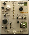
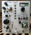
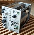
Template:Plugin Sidebar 2 The Tektronix 1L40 is a spectrum analyzer plug-in for 500-series scopes. It covers the frequency range from 1.5 GHz to 40 GHz.
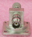
The front-end mixer of the 1L40 is a removable module. By default the 1L40 comes with a coaxial mixer, Tek part number 119-0096-00, which works up to 12.4 GHz. The 119-0096-00 contains a 1N415D detector diode.
Type 1L40 was produced for only 3 years, making it the shortest-lived letter-series plug-in.
- 12.4 GHz to 18 GHz requires the 119-0097-00.
- 18 GHz to 26.5 GHz requires the 119-0098-00.
- 26.5 GHz to 40 GHz requires the 119-0099-00.
Specifications
please add
Pictures
-
1L40 Front
-
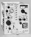
Front View from Catalog
-
Bent tooth on 1L40 tuning gear provides limit stop in both directions.
-
-
-
-
-
-
-
-
-
-
External Mixers and Adaptor
-
119-0097-00
-
119-0097-00
-
119-0098-00
-
119-0098-00
-
119-0099-00
-
119-0099-00
-
Front view
-
Threequarter view
-
Right side view. Note the housing for the removable input mixer at bottom left, and the tuned cavity for the 1st local oscillator at the top.
-
Left side view.
-
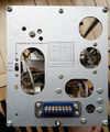
Rear view. Note the selector switch to adapt the sweep input voltage to different models in the 500 series range.
-
Bottom view.
-
Top view. Cavity for the 1st local oscillator is on the right, and the tuning mechanism is visible. IF filters and attenuators are in the can in the middle.
-
Input connector. This is the basic 1.5-12.4GHz input, which can be removed and replaced with an extension cable to waveguide mixers for higher frequencies.
-
Closeup of RF centre frequency dial. Fundamental range is at the bottom with harmonics above.
-
Closeup of part of the dispersion range switch assembly. Note the two little fingers attached to the shaft which operate the toggle switch.
-
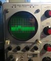
1L40 in 535A mainframe tuned to 2100MHz cellular band showing signals. 5MHz/div dispersion.
-
Tuned to 2100MHz cellular band (5MHz/div dispersion) showing 3G data downlinks from various operators. From the right: Orange, T-Mobile, Plus and Play. Photo taken in Warsaw, Poland, January 2018.
-
Signals displayed straight through the plugin's 150-250MHz IF. Dispersion 5MHz/div, centre frequency 200MHz. The peak on the left is the local DAB radio multiplex on channel 6B, 183.648MHz. The hump to the right of that looks like a DVB-T multiplex on channel 7, but I can't identify it. Photo taken in Warsaw, Poland, January 2018.
