134: Difference between revisions
m (minor tweaks) |
No edit summary |
||
| (11 intermediate revisions by 3 users not shown) | |||
| Line 12: | Line 12: | ||
|manuals= | |manuals= | ||
* [[Media:070-0524-00.pdf|Tektronix 134 Manual (early)]] | * [[Media:070-0524-00.pdf|Tektronix 134 Manual (early)]] | ||
* [[Media:070-0990-00.pdf|Tektronix 134 Manual ( | * [[Media:070-0990-00.pdf|Tektronix 134 Manual "SN6540 and up"]] | ||
* [[Media:070-0990-00 sn6620.pdf|Tektronix 134 Manual "SN6620 and up"]] | |||
* [[Media:070-0990-01.pdf|Tektronix 134 Manual (Final version, 1977)]] | |||
* [[Media:Tek_134_1971_cat.pdf|Tektronix 134 Description in 1971 Catalog]] | * [[Media:Tek_134_1971_cat.pdf|Tektronix 134 Description in 1971 Catalog]] | ||
* [[Media:Tek 134 fcp aug 1966b.pdf|Tektronix Type 134 Factory Calibration Procedure, August 1966]] | * [[Media:Tek 134 fcp aug 1966b.pdf|Tektronix Type 134 Factory Calibration Procedure, August 1966]] | ||
}} | }} | ||
The '''Tektronix 134''' current probe amplifier interfaces a [[P6019]], [[P6020]], [[P6021]] or [[P6022]] current probe to the voltage input of an oscilloscope. It was designed by [[Hans Springer]]. | The '''Tektronix 134''' current probe amplifier interfaces a [[P6019]], [[P6020]], [[P6021]] or [[P6022]] current probe to the voltage input of an oscilloscope. It also has a VOLTS ONLY setting of the input attenuator switch that provides a voltage gain of 125 or 50, depending on the position of the probe selector switch, with a 50 Ω input impedance. It was designed by [[Hans Springer]]. Early versions, up thru S/N 6539, had the switch positions labeled only for the [[P6019]] & [[P6020]] probes but these early versions are still compatible with the later [[P6021]] & [[P6022]] probes introduced in 1969. | ||
Each 134 came with its own dedicated power supply | Each 134 came with its own separate, dedicated power supply using the same Tektronix proprietary coaxial connector as that used in the Type [[131]]s and its [[015-027 | power supplies ]], but the [[131]] and 134 power supplies are ''not'' interchangeable. For more information on the power supplies for the Type 134 see the separate Type [[015-0058-01 | 134 Power Supplies ]] page. | ||
{{BeginSpecs}} | |||
{{Spec | Current Ranges | 1 mA/Div to 1 A/Div, 1−2−5 (scope at 50 mV/Div) }} | |||
{{Spec | Voltage Gain | 125 in P6019/P6021 switch position }} | |||
{{Spec | Voltage Gain | 50 in P6020/P6022 switch position }} | |||
{{Spec | Bandwidth | 10 Hz to 30 MHz in P6019/P6021 x120 mode }} | |||
{{Spec | Bandwidth | 8 Hz to 54 MHz in P6020/P6022 x50 mode }} | |||
{{EndSpecs}} | |||
==Bandwidths== | |||
{| class="wikitable" | |||
|- | |||
! | |||
! P6019 + <br>Type 134 | |||
! P6019 + <br>Passive<br>Termination | |||
! P6021 + <br>Type 134 | |||
! P6021 + <br>Passive<br>Termination | |||
! P6020 + <br>Type 134 | |||
! P6020 + <br>Passive<br>Termination | |||
! P6022 + <br>Type 134 | |||
! P6022 + <br>Passive<br>Termination | |||
|- | |||
! Low Frequency -3 dB | |||
|align=right|≤12 Hz | |||
|align=right|≤120 Hz<br>≤450 Hz | |||
|align=right|≤12 Hz | |||
|align=right|≤120 Hz<br>≤450 Hz | |||
|align=right|≤100 Hz | |||
|align=right|≤935 Hz<br>≤8500 kHz | |||
|align=right|≤100 Hz | |||
|align=right|≤935 Hz<br>≤8500 kHz | |||
|- | |||
! High Frequency -3dB | |||
|align=right| ≥40 MHz | |||
|align=right| ≥60 MHz | |||
|align=right| ≥36 MHz* | |||
|align=right| ≥52 MHz* | |||
|align=right| ≥70 MHz | |||
|align=right| ≥200 MHz | |||
|align=right| ≥54 MHz* | |||
|align=right| ≥90 MHz* | |||
|- | |||
! Max. Continuous Current | |||
|align=right| 15 A<sub>p-p</sub> | |||
|align=right| 15 A<sub>p-p</sub> | |||
|align=right| 15 A<sub>p-p</sub> | |||
|align=right| 15 A<sub>p-p</sub> | |||
|align=right| 6 A<sub>p-p</sub> | |||
|align=right| 6 A<sub>p-p</sub> | |||
|align=right| 6 A<sub>p-p</sub> | |||
|align=right| 6 A<sub>p-p</sub> | |||
|- | |||
|} | |||
(*These figures are system numbers and take into account the effects of a 100 MHz oscilloscope. There appears to be little or no electrical difference between the early and late families of the Tektronix current probes. P6019 & P6020 figures are from from the 1968 Tektronix catalog and do not include the oscilloscope. it's hard to understand some of them given the stated 54 MHz bandwidth of the Type 134.) | |||
Note that in every case, the passive termination is slightly better for high frequency response, while the Type 134 improves the low frequency response. | |||
==Links== | ==Links== | ||
| Line 70: | Line 116: | ||
Tek134-int3.jpg | Tek134-int3.jpg | ||
Tek 134 schem.png | Schematic | Tek 134 schem.png | Schematic | ||
134 latest.jpg | latest version with wall wart PS | |||
</gallery> | </gallery> | ||
Revision as of 03:01, 28 April 2024

The Tektronix 134 current probe amplifier interfaces a P6019, P6020, P6021 or P6022 current probe to the voltage input of an oscilloscope. It also has a VOLTS ONLY setting of the input attenuator switch that provides a voltage gain of 125 or 50, depending on the position of the probe selector switch, with a 50 Ω input impedance. It was designed by Hans Springer. Early versions, up thru S/N 6539, had the switch positions labeled only for the P6019 & P6020 probes but these early versions are still compatible with the later P6021 & P6022 probes introduced in 1969.
Each 134 came with its own separate, dedicated power supply using the same Tektronix proprietary coaxial connector as that used in the Type 131s and its power supplies , but the 131 and 134 power supplies are not interchangeable. For more information on the power supplies for the Type 134 see the separate Type 134 Power Supplies page.
Key Specifications
| Current Ranges | 1 mA/Div to 1 A/Div, 1−2−5 (scope at 50 mV/Div) |
|---|---|
| Voltage Gain | 125 in P6019/P6021 switch position |
| Voltage Gain | 50 in P6020/P6022 switch position |
| Bandwidth | 10 Hz to 30 MHz in P6019/P6021 x120 mode |
| Bandwidth | 8 Hz to 54 MHz in P6020/P6022 x50 mode |
Bandwidths
| P6019 + Type 134 |
P6019 + Passive Termination |
P6021 + Type 134 |
P6021 + Passive Termination |
P6020 + Type 134 |
P6020 + Passive Termination |
P6022 + Type 134 |
P6022 + Passive Termination | |
|---|---|---|---|---|---|---|---|---|
| Low Frequency -3 dB | ≤12 Hz | ≤120 Hz ≤450 Hz |
≤12 Hz | ≤120 Hz ≤450 Hz |
≤100 Hz | ≤935 Hz ≤8500 kHz |
≤100 Hz | ≤935 Hz ≤8500 kHz |
| High Frequency -3dB | ≥40 MHz | ≥60 MHz | ≥36 MHz* | ≥52 MHz* | ≥70 MHz | ≥200 MHz | ≥54 MHz* | ≥90 MHz* |
| Max. Continuous Current | 15 Ap-p | 15 Ap-p | 15 Ap-p | 15 Ap-p | 6 Ap-p | 6 Ap-p | 6 Ap-p | 6 Ap-p |
(*These figures are system numbers and take into account the effects of a 100 MHz oscilloscope. There appears to be little or no electrical difference between the early and late families of the Tektronix current probes. P6019 & P6020 figures are from from the 1968 Tektronix catalog and do not include the oscilloscope. it's hard to understand some of them given the stated 54 MHz bandwidth of the Type 134.)
Note that in every case, the passive termination is slightly better for high frequency response, while the Type 134 improves the low frequency response.
Links
- Tek 134 @ analogdesign.be (preserved at archive.org) − photos and description
Prices
| Year | 1970 | 1974 | 1984 | 1986 |
|---|---|---|---|---|
| Catalog price | $209 | $265 | $625 | $625 |
| In 2022 Dollars | $1,600 | $1,600 | $1,800 | $1,700 |
Pictures
-

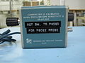
134 front, 1966−1969 model (P6019/P6020-only switch label)
-

134 front, 1969+ model
-

-
-

-

-
-
-
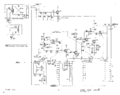
Schematic
-
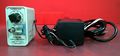
latest version with wall wart PS


Measurements
Comparison of P6022 with passive termination @ 10 mA/Div (top trace) vs. P6021+134 (bottom trace). Signal is a sawtooth from a HP3325A @ 5 Vp-p into 50 Ω = 100 mAp-p.
-
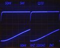
100 Hz
-
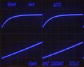
1 kHz
-
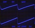
10 kHz


