6R1A: Difference between revisions
No edit summary |
No edit summary |
||
| (12 intermediate revisions by 3 users not shown) | |||
| Line 1: | Line 1: | ||
{{Plugin Sidebar | {{Plugin Sidebar | ||
|manufacturer=Tektronix | |||
summary=Digital readout plug-in | | |series=567 | ||
image=6r1a_front.JPG | | |type=6R1A | ||
caption=6R1A | |summary=Digital readout plug-in | ||
|image=6r1a_front.JPG | |||
introduced=1964 | | |caption=Tektronix 6R1A | ||
discontinued= | |introduced=1964 | ||
manuals= | |discontinued=1972 | ||
* [ | |designers= | ||
* [ | |manuals= | ||
* [ | * [[Media:070-411.pdf|Tektronix 6R1A Manual]] (PDF) | ||
* [[Media:Tek 6r1a 1968 catalog.pdf|Tektronix 6R1A in 1968 Catalog]] | |||
* [[Media:Tek 6r1a notes ocr.pdf|Tektronix 6R1A Notes (OCR)]] | |||
* [[Media:Tek 6R1A and system calibration.pdf|Tektronix 6R1A and System Calibration (OCR PDF, 26M)]] | |||
}} | }} | ||
The '''Tektronix | The '''Tektronix 6R1A''' is a plug-in for the [[567]] oscilloscope. | ||
The 6R1A provides digital readout of time and voltage measurements | It replaced the [[6R1]]. | ||
on waveforms. | The 6R1A provides digital readout of time and voltage measurements on waveforms. | ||
The 6R1A is a counter and a comparator. | The 6R1A (and the 567 in general) is oriented toward sampling measurements. | ||
are used as a ramp-compare ADC. | The 6R1A is a counter and a comparator. | ||
To digitize analog voltages, the counter and comparator are used as a ramp-compare ADC. | |||
Card Q (Voltmeter) contains a 1 MHz crystal oscillator. | |||
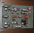
The counters (Card A) are made of flip-flops made of [[2N1754]] Germanium PNP transistors. | The counters (Card A) are made of flip-flops made of [[2N1754]] Germanium PNP transistors. | ||
The 6R1A differs sightly from the 6R1, mainly in what determines the 0% zone. | The 6R1A differs sightly from the 6R1, mainly in what determines the 0% zone. | ||
In the 6R1, the 0% zone is always the leftmost major division of the | In the 6R1, the 0% zone is always the leftmost major division of the trace. | ||
trace. | In the 6R1A, the horizontal position of the 0% zone can be set arbitrarily. | ||
Internally, the 6R1A differs from the 6R1 in how its functions are implemented. | Internally, the 6R1A differs from the 6R1 in how its functions are implemented. | ||
6R1 uses about seven tunnel diodes while the 6R1A uses only two tunnel diodes. | The 6R1 uses about seven tunnel diodes while the 6R1A uses only two tunnel diodes. | ||
6R1 uses several Nuvistor tubes. | The 6R1 uses several Nuvistor tubes. | ||
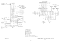
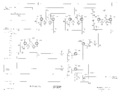
Take for example the front end of the SIGNAL COMPARATOR board. | In the 6R1A many tubes were replaced by transistors. | ||
[[7586]] Nuvistor triodes. | Take for example the front end of the SIGNAL COMPARATOR board. | ||
In the 6R1 it uses two [[7586]] Nuvistor triodes. | |||
In the 6R1A it is two NPN transistors. | |||
The digital display of the Tektronix 6R1 is composed of four [[Burroughs B5092]] Nixie | The digital display of the Tektronix 6R1 is composed of four [[Burroughs B5092]] Nixie tubes for the digits, | ||
tubes for the digits, and one | and one [http://www.tube-tester.com/sites/nixie/data/B-5094/b-5094.htm Burroughs B5094] Nixie tube for the units. | ||
[http://www.tube-tester.com/sites/nixie/data/B-5094/b-5094.htm Burroughs B5094] Nixie tube for the units. | |||
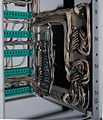
There is an extender plug-in, the [[067-0505-00]], that allows a 6R1 or 6R1A to be operated | There is an extender plug-in, the [[067-0505-00]], that allows a 6R1 or 6R1A to be operated outside the plug-in bay of the 567 for maintenance purposes. | ||
outside the plug-in bay of the 567 for maintenance purposes. | There are extension cards, the 012-067 and 012-068 (shown below), that allow the circuit cards in the 6R1 to be accessed for maintenance while the instrument is powered up. | ||
There are extension cards, the 012-067 and 012-068 (shown below), | |||
that allow the circuit cards in the 6R1 to be accessed for maintenance while the instrument is powered up. | |||
==Specifications== | ==Specifications== | ||
| Line 43: | Line 47: | ||
==Pictures== | ==Pictures== | ||
<gallery> | <gallery> | ||
6r1a_front.JPG|Front | |||
6r1a_left.JPG|Left | |||
6r1a_right.JPG|Right | |||
6r1a_top.JPG|Top | |||
6r1a_bottom.JPG|Bottom | |||
6r1a_rear.JPG|Rear | |||
6r1a_card_a.JPG|Card A (counter) | |||
6r1a_card_a_back.JPG|Card A (counter) | |||
6r1a_card_b.JPG|Card B (div 1, 2, 5) | |||
6r1a_card_b_back.JPG|Card B (div by 1, 2, 5) | |||
6r1a_card_f.JPG|Card F (upper-limit no-go) | |||
6r1a_card_f_back.JPG|Card F (upper-limit no-go) | |||
6r1a_card_g.JPG|Card G (lower-limit no-go) | |||
6r1a_card_g_back.JPG|Card G (lower-limit no-go) | |||
6r1a_card_h.JPG|Card H (limit light driver) | |||
6r1a_card_h_back.JPG|Card H (limit light driver) | |||
6r1a_card_i.JPG|Card I (div by 10) | |||
6r1a_card_i_back.JPG|Card I (div by 10) | |||
6r1a_card_j.JPG|Card J (analog display) | |||
6r1a_card_j_back.JPG|Card J (analog display) | |||
6r1a_card_m.JPG|Card M (master gate) | |||
6r1a_card_m_back.JPG|Card M (master gate) | |||
6r1a_card_n.JPG|Card N (signal comparator) | |||
6r1a_card_n_back.JPG|Card N (signal comparator) | |||
6r1a_card_o.JPG|Card O (0% zone) | |||
6r1a_card_o_back.JPG|Card O (0% zone) | |||
6r1a_card_p.JPG|Card P (memory) | |||
6r1a_card_p_back.JPG|Card P (memory) | |||
6r1a_card_q.JPG|Card Q (voltmeter) | |||
6r1a_card_q_back.JPG|Card Q (voltmeter) | |||
6r1a_rear_connector_inside.JPG|Rear Connector | |||
6r1a connectors to indicator unit.png|Connectors to Indicator Unit | |||
6r1a plug-in card connectors.png|Plug-in Card Connectors | |||
6r1a signal comparator schem.png|Signal Comparator | |||
6r1a master gate schem.png|Master Gate | |||
6r1a voltmeter schem.png|Voltmeter | |||
6r1a lower limit no-go schem.png|Lower Limit No-Go | |||
6r1a upper limit no-go schem.png|Upper Limit No-Go | |||
6r1a limit light driver schem.png|Limit Light Driver | |||
6r1a divide by 10.png|Divide By 10 | |||
6r1a divide 1 2 5 schem.png|Divide By 1, 2, 5 | |||
6r1a counter schem.png|Counter | |||
6r1a analog display schem.png|Analog Display | |||
6r1a 0 percent zone schem.png|0 Percent Zone | |||
6r1a 0 and 100 memories schem.png|0 and 100 Percent Memories | |||
6r1a external readout connector j31.png|External Readout Connector J33 | |||
6r1a external programming connector j34.png|External Programming Connector J34 | |||
Tek_012-067_012-068_1964_cat.jpg|012-067_and 012-068 Extender Cards for Maintenance | |||
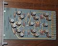
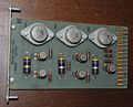
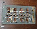
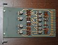
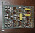
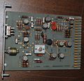
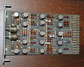
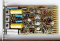
Tek 6r1a series p model 7 component.jpg|Series P Memory Card, Model 7, Component Side | |||
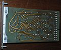
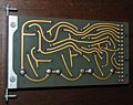
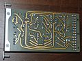
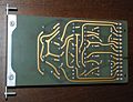
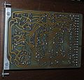
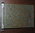
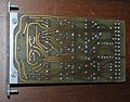
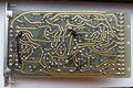
Tek 6r1a series p model 7 back.jpg|Series P Memory Card, Model 7, Back Side | |||
Tek 6r1a series p model 7 bracket.jpg|Series P Memory Card, Model 7, Bracket | |||
</gallery> | </gallery> | ||
[[Category:560 series plugins]] | [[Category:560 series plugins]] | ||
Latest revision as of 18:08, 9 December 2023

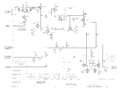
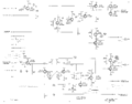
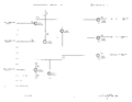
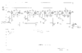
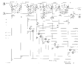
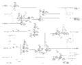
The Tektronix 6R1A is a plug-in for the 567 oscilloscope. It replaced the 6R1. The 6R1A provides digital readout of time and voltage measurements on waveforms. The 6R1A (and the 567 in general) is oriented toward sampling measurements. The 6R1A is a counter and a comparator. To digitize analog voltages, the counter and comparator are used as a ramp-compare ADC. Card Q (Voltmeter) contains a 1 MHz crystal oscillator. The counters (Card A) are made of flip-flops made of 2N1754 Germanium PNP transistors.
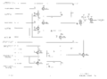
The 6R1A differs sightly from the 6R1, mainly in what determines the 0% zone. In the 6R1, the 0% zone is always the leftmost major division of the trace. In the 6R1A, the horizontal position of the 0% zone can be set arbitrarily.
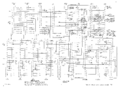
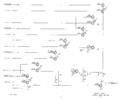
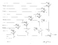
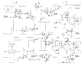
Internally, the 6R1A differs from the 6R1 in how its functions are implemented. The 6R1 uses about seven tunnel diodes while the 6R1A uses only two tunnel diodes. The 6R1 uses several Nuvistor tubes. In the 6R1A many tubes were replaced by transistors. Take for example the front end of the SIGNAL COMPARATOR board. In the 6R1 it uses two 7586 Nuvistor triodes. In the 6R1A it is two NPN transistors.
The digital display of the Tektronix 6R1 is composed of four Burroughs B5092 Nixie tubes for the digits, and one Burroughs B5094 Nixie tube for the units.
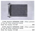
There is an extender plug-in, the 067-0505-00, that allows a 6R1 or 6R1A to be operated outside the plug-in bay of the 567 for maintenance purposes. There are extension cards, the 012-067 and 012-068 (shown below), that allow the circuit cards in the 6R1 to be accessed for maintenance while the instrument is powered up.
Specifications
please add
Pictures
-
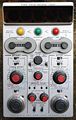
Front
-
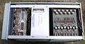
Left
-
Right
-
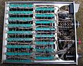
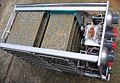
Top
-
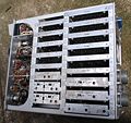
Bottom
-
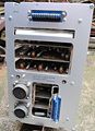
Rear
-
Card A (counter)
-
Card A (counter)
-
Card B (div 1, 2, 5)
-
Card B (div by 1, 2, 5)
-
Card F (upper-limit no-go)
-
Card F (upper-limit no-go)
-
Card G (lower-limit no-go)
-
Card G (lower-limit no-go)
-
Card H (limit light driver)
-
Card H (limit light driver)
-
Card I (div by 10)
-
Card I (div by 10)
-
Card J (analog display)
-
Card J (analog display)
-
Card M (master gate)
-
Card M (master gate)
-
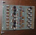
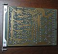
Card N (signal comparator)
-
Card N (signal comparator)
-
Card O (0% zone)
-
Card O (0% zone)
-
Card P (memory)
-
Card P (memory)
-
Card Q (voltmeter)
-
Card Q (voltmeter)
-
Rear Connector
-
Connectors to Indicator Unit
-
Plug-in Card Connectors
-
Signal Comparator
-
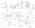
Master Gate
-
Voltmeter
-
Lower Limit No-Go
-
Upper Limit No-Go
-
Limit Light Driver
-
Divide By 10
-
Divide By 1, 2, 5
-
Counter
-
Analog Display
-
0 Percent Zone
-
0 and 100 Percent Memories
-
External Readout Connector J33
-
External Programming Connector J34
-
012-067_and 012-068 Extender Cards for Maintenance
-
Series P Memory Card, Model 7, Component Side
-
Series P Memory Card, Model 7, Back Side
-

Series P Memory Card, Model 7, Bracket


