4S2: Difference between revisions
| Line 27: | Line 27: | ||
Tek 4s2a sampler.png|42SA sampler schematic | Tek 4s2a sampler.png|42SA sampler schematic | ||
Tek 4s2a pulse gen.png|42SA pulse generator schematic | Tek 4s2a pulse gen.png|42SA pulse generator schematic | ||
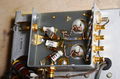
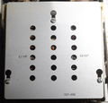
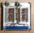
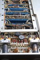
Tek 4s2 avalanche pulse components.jpg|4S2 | Tek 4s2 avalanche pulse components.jpg|4S2 Pulse Generator | ||
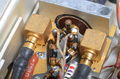
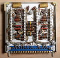
Tek 4s2 avalanche pulse1.jpg|4S2 | Tek 4s2 avalanche pulse1.jpg|4S2 Pulse Generator | ||
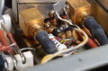
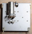
Tek 4s2 avalanche pulse2.jpg|4S2 | Tek 4s2 avalanche pulse2.jpg|4S2 Pulse Generator | ||
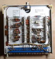
Tek 4s2 avalanche pulse4.jpg|4S2 | Tek 4s2 avalanche pulse4.jpg|4S2 Pulse Generator | ||
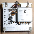
Tek 4s2 sampler.jpg|4S2 Sampler | Tek 4s2 sampler.jpg|4S2 Sampler | ||
Tek 4s2 sampler2.jpg|4S2 Sampler | Tek 4s2 sampler2.jpg|4S2 Sampler | ||
| Line 41: | Line 41: | ||
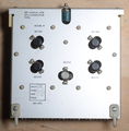
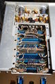
Tek 4s2 dual-trace outside.jpg|Dual Trace | Tek 4s2 dual-trace outside.jpg|Dual Trace | ||
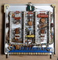
Tek 4s2 dual-trace components.jpg|Dual Trace | Tek 4s2 dual-trace components.jpg|Dual Trace | ||
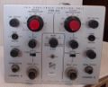
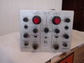
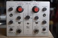
Tek 4s2 front straight.jpg | Tek 4s2 front straight.jpg|4S2 | ||
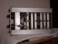
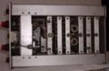
Tek 4s2 left front inside.jpg | Tek 4s2 left front inside.jpg|4S2 | ||
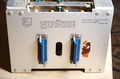
Tek 4s2 input connector.jpg | Tek 4s2 input connector.jpg|4S2 | ||
Tek 4s2 front right wiring.jpg | Tek 4s2 front right wiring.jpg|4S2 | ||
Tek 4s2 front 32.jpg | Tek 4s2 front 32.jpg|4S2 | ||
Tek 4s2 front bottom.jpg | Tek 4s2 front bottom.jpg|4S2 | ||
Tek 4s2 bottom wiring.jpg | Tek 4s2 bottom wiring.jpg|4S2 | ||
Tek 4s2 rear.jpg|4S2 Rear | Tek 4s2 rear.jpg|4S2 Rear | ||
</gallery> | </gallery> | ||
Revision as of 21:29, 14 December 2017
Template:Plugin Sidebar 2 The Tektronix 4S2 is a two-channel sampling vertical plug-in for the 661. Signals enter the 4S2 through GR-874 connectors on the front panel. Unlike the 4S1, the 4S2's signal path does not contain a delay line between the input connector and the sampler. This has the advantage of maintaining higher pulse fidelity and thus higher bandwidth. It has the disadvantage of making it impossible to see the leading edge of the triggering event unless a pre-trigger is used.
The 4S2 uses a four-diode sampling bridge. The 4S2A uses a two-diode sampling bridge. This design change is discussed in the 4S2A Engineering Spec document linked below.
Pictures
-
-
-
-
-
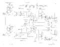
42SA sampler schematic
-
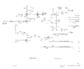
42SA pulse generator schematic
-
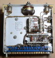
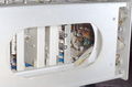
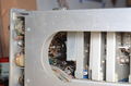
4S2 Pulse Generator
-
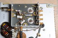
4S2 Pulse Generator
-
4S2 Pulse Generator
-
4S2 Pulse Generator
-
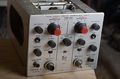
4S2 Sampler
-
4S2 Sampler
-
AC Amplifier
-
AC Amplifier
-
Memory
-
Memory
-

Inverter
-
Inverter
-
Dual Trace
-
Dual Trace
-
4S2
-
4S2
-
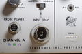
4S2
-
4S2
-
4S2
-
4S2
-
4S2
-
4S2 Rear


