7L5/Repairs: Difference between revisions
Jump to navigation
Jump to search
No edit summary |
No edit summary |
||
| Line 1: | Line 1: | ||
=Intermittent Switch Operation= | |||
=Front Panel Disassembly= | |||
to be explained soon | |||
=Pictures= | |||
==Front Panel== | ==Front Panel== | ||
Revision as of 21:40, 21 June 2020
Intermittent Switch Operation
Front Panel Disassembly
to be explained soon
Pictures
Front Panel
-
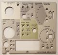
Front panel Overlay (Military version without B-(save A) )
-
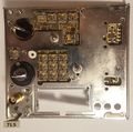
Front panel with overlay removed in frame
-
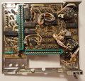
Front panel backside in frame
-
Front panel frontside
-
Front panel backside
-
Front panel backside with Reference Level switch partially disassembled
-
Front panel backside with Reference Level switch removed. Parts of switch with sliding contacts shown below.
-
Front panel frontside with Reference Level switch removed. Switch gold contact traces visible
-
Span and Time/Div. switch backsides
-
Span and Time/Div. switch sideview
-
Front panel with Time/Div. switch removed. Note plastic spacer on the right
-
Front panel plastic spacer for Time/Div. switch installed in correct orientation, ready for switch installation.


