519: Difference between revisions
No edit summary |
(Annotate right pic) |
||
| Line 102: | Line 102: | ||
Image:519_adaptkit2.jpg|519 adapter kit case | Image:519_adaptkit2.jpg|519 adapter kit case | ||
Image:519 left.JPG | Image:519 left.JPG | ||
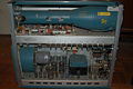
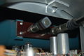
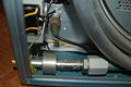
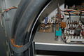
Image:519 right.JPG | Image:519 right.JPG|Delay line around the EHT section | ||
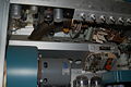
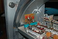
Image:519 crt defl.jpg|CRT deflection trimmers* | Image:519 crt defl.jpg|CRT deflection trimmers* | ||
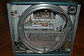
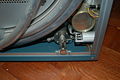
Image:519 blower.JPG|Blower and duct | Image:519 blower.JPG|Blower and duct | ||
Revision as of 04:55, 25 November 2010
The Tektronix 519 is a high-speed oscilloscope made by Tektronix from 1961 to the early 1970's. It was designed by Cliff Moulton, who also designed the Type 130 LC Meter. The 519 is very unusual in that it does not contain vertical amplifiers. The input signal is passively connected to the distributed vertical deflection plates of the CRT, which are driven single-ended. This allows the scope to have 1GHz bandwidth. The vertical deflection factor is 10 V/cm. The input to the 519 has an impedance of 125 ohms. The input connector is a special 125-ohm GR connector that is neither electrically nor mechanically compatible with the much more common 50-ohm GR connector.
To allow viewing of the leading edge of pulses, there is a rigid coaxial 45 nanosecond delay line between the input and the CRT.

The sweep is triggered using a 20mA, 4pF tunnel diode. The horizontal deflection signal of a 519 is generated by a 4CX250F external anode, radial-beam tube that is cooled by forced air sent from a blower through a duct. The datasheet for the 4CX250F is here:
The total accelerating voltage of the 519 is 24 kilovolts.
The 519 contains a calibration step generator that produces voltage steps with 100 picosecond rise time.
The physical construction and styling of the 519 differs from that of the other Tek scopes of the same period. There are multiple reasons for this. First, it has an unusually long CRT. Also, the large 125-ohm coaxial delay line (seen in the photo) had to fit inside the cabinet. Finally, the 519 has an extra-large power transformer and a large blower for the 4CX250 tube. The mass of these extra components necessitated a larger, sturdier cabinet than, for example, the 545. The sheet aluminum used in the case of the 519 is thicker than that of the other Tek scopes of the period.
The 519 came with two different bezels. Pictured in Tek Catalog 20 through 26 is the early version which was actually a camera mount designed to be compatible with the C19 camera. It had a unique removable part with a graticule that could be slid down such that it would not be in between the CRT beam and the camera lens. Most of the non-used area of the CRT faceplate was covered by the black plastic material of the graticule cover. This graticule cover was changed slightly as is shown in the pictures of the 519 in Tek Catalogs 27 and later. It still was designed to mount the C19 camera. For what reason was the bezel design changed?
The 519 is probably the only Tek scope to come standard with a camera mount for a bezel. You had to buy camera mounting frames as accessories for the other scopes.
Early 519's in the '61-'66 period were calibrated in Plant 2 in a group managed by Bob Randall. Three of the men calibrating 519's in that period were Stan Griffiths, Dick Bellamy, and John A. (What is John's last name?) During this period, Cliff Moulton would visit the calibration operation to answer any questions that would arise as the scopes were being prepared for shipment to customers.
Later 519's were calibrated at Plant 2 Test-Final in a group managed by Jack Lyngdal. Two of the calibration people that worked there were Norm Jenkins and Jack. (What is Jack's last name?) Another man who calibrated 519's in this later period was Mark Balcom.
Tektronix Catalog 22 (mid'63-mid'64) refers to a modified 519 with response extended to 3GHz : "DC-to-3 GIGACYCLE OSCILLOSCOPE This modified Type 519 Oscilloscope incorporates a coaxial-deflection crt to achieve a risetime of 0.13nsec, corresponding to a 3000-Mc bandwidth. Deflection factor is approximately 180v/cm. Usable viewing area is 2x4 cm. Consult your FE to learn about the advantages, limitations, and delivery time on this or other modified instruments." The following paper includes a chart that mentions in Figure 10 the 3GHz 519C introduced in 1963. The 519C is either very rare or extinct or was never actually made.
Manual:
Entry in 1969 catalog:
- http://w140.com/kurt/tek69/112.jpeg
- http://w140.com/kurt/tek69/113.jpeg
- http://w140.com/kurt/tek69/114.jpeg
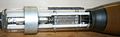
The 519 came with a set of adapters performing various functions such as interfacing the 125-ohm input impedance of the 519 with the more common 50-ohm impedance of many cables and instruments.
-
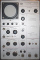
519 front view
-

519 adapter kit
-
519 adapter kit case
-
-
Delay line around the EHT section
-
CRT deflection trimmers*
-
Blower and duct
-
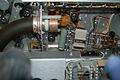
Sweep tube and duct
-
Vertical terminator
-
Trigger pickoff
-
-
-
-


- CRT photo courtesy of [collection.archivist.info]