File:154-0784-00.jpg: Difference between revisions
No edit summary |
No edit summary |
||
| Line 1: | Line 1: | ||
Below is a tube assembled with a reading hybrid microassembly. The upper row of the frames shows the sequence of installation of this microassembly on the tube (one picture is skipped there; one more contact spring is installed between the holder and the tube itself). | |||
The middle side frames show the actual gun itself, and its deflecting plates. Despite the fact that the tubes are relatively high-frequency (the band of the device is 80 MHz), the deflecting "Y" plates are monolithic. Quartz "X" deflection plates in their size demonstrate their functional: the centering of the beam, and not a horizontal scan. | |||
The most interesting is shown on two small adjacent side frames on the left. There, fragments of the semiconductor wafer placed inside the bulb are visible. In this tube, instead of accumulating charge on the target and further reading it with a second searchlight, the beam of the writing spotlight directly affects the photodiode array. Before us, we can say, an electron-bombarded semiconductor lamp. The photos are not very sharp: the array is placed on the bottom of a metal cup, and even covered with a diaphragm. It's a very ungrateful thing to photograph a thin structure at a great angle through the wall of a glass cylinder. | |||
If the other tubes from Tektronix digitizers, which I held in my hands, were graphecon by the principle of action, that is, scan-converter; this CRT is coding (CCRT) by its operating principle. | |||
12 rows of photodiodes, each of which corresponds to one bit of the output signal, are covered by masks that form the coding table. Deflected by the input signal along the Y-axis, the ribbon-shaped beam passes through the window line in the mask. The line cut by the mask falls on the photodiode columns already encoded in binary code. It remains only to read the value from the columns. In the next cycle, another value of the input signal is read, then again and again. The sampling frequency varies from 1 Hz to 200 MHz. | |||
Such a system has an advantage in digitizers with a relatively low signal bandwidth. In fact, the extension of the frequency band of the ADC, in full accordance with the Kotel'nikov theorem, will require a corresponding increase in the sampling frequency. All this will shorten the time of the steady state of the bits, and the reading system will be drowned by the data stream. Simultaneously, with the same sensitivity of photodiodes, an increase in the recording speed will require an increase in the beam current, and this is fraught with rapid degradation of the semiconductor. At the same time, sampling itself is faster: the oscillogram is directly read into the device's memory as the horizontal sweep goes straight. There is no need to wait for the completion of the full sweep of the reading gun after each cycle of recording the image on the target, it is possible to digitize the signal in real time. | |||
Latest revision as of 22:08, 10 July 2017
Below is a tube assembled with a reading hybrid microassembly. The upper row of the frames shows the sequence of installation of this microassembly on the tube (one picture is skipped there; one more contact spring is installed between the holder and the tube itself).
The middle side frames show the actual gun itself, and its deflecting plates. Despite the fact that the tubes are relatively high-frequency (the band of the device is 80 MHz), the deflecting "Y" plates are monolithic. Quartz "X" deflection plates in their size demonstrate their functional: the centering of the beam, and not a horizontal scan. The most interesting is shown on two small adjacent side frames on the left. There, fragments of the semiconductor wafer placed inside the bulb are visible. In this tube, instead of accumulating charge on the target and further reading it with a second searchlight, the beam of the writing spotlight directly affects the photodiode array. Before us, we can say, an electron-bombarded semiconductor lamp. The photos are not very sharp: the array is placed on the bottom of a metal cup, and even covered with a diaphragm. It's a very ungrateful thing to photograph a thin structure at a great angle through the wall of a glass cylinder.
If the other tubes from Tektronix digitizers, which I held in my hands, were graphecon by the principle of action, that is, scan-converter; this CRT is coding (CCRT) by its operating principle.
12 rows of photodiodes, each of which corresponds to one bit of the output signal, are covered by masks that form the coding table. Deflected by the input signal along the Y-axis, the ribbon-shaped beam passes through the window line in the mask. The line cut by the mask falls on the photodiode columns already encoded in binary code. It remains only to read the value from the columns. In the next cycle, another value of the input signal is read, then again and again. The sampling frequency varies from 1 Hz to 200 MHz.
Such a system has an advantage in digitizers with a relatively low signal bandwidth. In fact, the extension of the frequency band of the ADC, in full accordance with the Kotel'nikov theorem, will require a corresponding increase in the sampling frequency. All this will shorten the time of the steady state of the bits, and the reading system will be drowned by the data stream. Simultaneously, with the same sensitivity of photodiodes, an increase in the recording speed will require an increase in the beam current, and this is fraught with rapid degradation of the semiconductor. At the same time, sampling itself is faster: the oscillogram is directly read into the device's memory as the horizontal sweep goes straight. There is no need to wait for the completion of the full sweep of the reading gun after each cycle of recording the image on the target, it is possible to digitize the signal in real time.
File history
Click on a date/time to view the file as it appeared at that time.
| Date/Time | Thumbnail | Dimensions | User | Comment | |
|---|---|---|---|---|---|
| current | 21:51, 10 July 2017 | 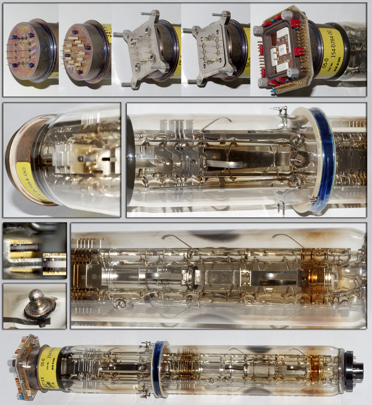 | 1,280 × 1,393 (379 KB) | Vladimir (talk | contribs) |
You cannot overwrite this file.
File usage
The following page uses this file: