021-0374-00: Difference between revisions
(Added some more pictures and description) |
(Added some more informations) |
||
| Line 31: | Line 31: | ||
==Pictures== | ==Pictures== | ||
<gallery> | <gallery> | ||
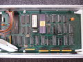
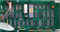
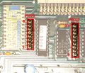
Tek_021_0374_00_Front2.jpg | Tek_021_0374_00_Front2.jpg|Front view of an early GPIB Decoder | ||
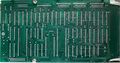
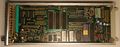
Tek 021-0374-00 7.jpg | Tek 021-0374-00 7.jpg|Front view of a late GPIB Decoder | ||
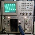
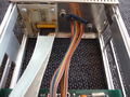
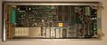
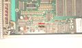
Tek 021-0374-00 8.jpg | Tek 021-0374-00 8.jpg| GPIB Decoder with [[7A16P]] & [[7B90P]] in a [[7854]] | ||
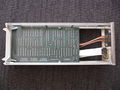
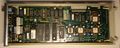
Tek 021-0374-00 1.jpg | Tek 021-0374-00 1.jpg|Left side of the GPIB decoder | ||
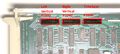
Tek 021-0374-00 2.jpg | Tek 021-0374-00 2.jpg|Left side of the GPIB decoder closeup (late version) | ||
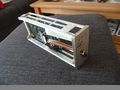
Tek 021-0374-00 3.jpg | Tek 021-0374-00 3.jpg | ||
Tek 021-0374-00 4.jpg | Tek 021-0374-00 4.jpg | ||
| Line 50: | Line 50: | ||
===Location of electrical components=== | ===Location of electrical components=== | ||
<gallery> | <gallery> | ||
Tek_7A16P_late.jpg|A late version of the 7A16P plugin is needed | Tek_7A16P_late.jpg|A late version of the [[7A16P]] plugin is needed | ||
Tek_7A16P_decoder_conn.jpeg|Location of the connectors for the GPIB decoder on a 7A16P | Tek_7A16P_decoder_conn.jpeg|Location of the connectors for the GPIB decoder on a [[7A16P]] | ||
Tek_7A29P_right_side.jpg|Right side of a 7A29P plugin | Tek_7A29P_right_side.jpg|Right side of a [[7A29P]] plugin | ||
Tek_7A29P_decoder_conn.jpeg|Location of the connectors for the GPIB decoder on a 7A29P | Tek_7A29P_decoder_conn.jpeg|Location of the connectors for the GPIB decoder on a [[7A29P]] | ||
Tek_7B90P_late.jpg|A late version of the 7B90P plugin is needed | Tek_7B90P_late.jpg|A late version of the [[7B90P]] plugin is needed | ||
Tek_7B90P_decoder_conn.jpeg|Location of the connectors for the GPIB decoder on a 7B90P | Tek_7B90P_decoder_conn.jpeg|Location of the connectors for the GPIB decoder on a [[7B90P]] | ||
Tek_7B90P_VR330.jpeg|Location of the zener diode V330 on a late 7B90P | Tek_7B90P_VR330.jpeg|Location of the zener diode V330 on a late [[7B90P]] | ||
Tek_021_0374_00_connectors.jpg|Location of the connectors to the plugins on the GPIB decoder | Tek_021_0374_00_connectors.jpg|Location of the connectors to the plugins on the GPIB decoder | ||
</gallery> | </gallery> | ||
| Line 62: | Line 62: | ||
===Mechanical components=== | ===Mechanical components=== | ||
<gallery> | <gallery> | ||
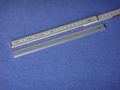
Tek 021-0374-00 10.jpg | Tek 021-0374-00 10.jpg|Bracket for mounting the programmable plugins to the decoder | ||
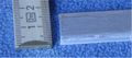
Tek 021-0374-00 11.jpg | Tek 021-0374-00 11.jpg|Bracket for mounting the programmable plugins to the decoder | ||
Tek 021-0374-00 12.jpg | Tek 021-0374-00 12.jpg|Bracket for mounting the programmable plugins to the decoder | ||
Tek 021-0374-00 13.jpg | Tek 021-0374-00 13.jpg|Bracket for mounting the programmable plugins to the decoder | ||
</gallery> | </gallery> | ||
Revision as of 11:11, 4 October 2020
Template:Plugin Sidebar 2 The Tektronix 021-0374-00 GPIB Decoder is a 7000-series plug-in designed to allow GPIB control of 7A16P or 7A29P programmable amplifiers and/or a 7B90P programmable time base module in a 7854 mainframe. (The manual warns that of all 7000 series mainframes, only the 7854 has adequate +5 V supply capacity.)
The -P type plugins were originally designed for the 7000 series digitizers like the 7912AD that have a built-in GPIB interface.
The 021-0374-00 replicates the functions of that interface, receiving commands from GPIB and translating them to the internal serial format expected by the plugins. It is based on a Motorola 6802 microcontroller and a TMS9914 GPIB interface chip.
The interface must be installed in the left horizontal (A timebase) bay. It addresses left vertical, right vertical and right horizontal plugins through GPIB sub-addresses 1, 2 and 3, respectively. Data connections from the 021-0374-00 the plugins require flat cables because the relevant bus lines are n/c on the 7854 backplane.
Links
Pictures
-
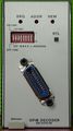
Front view of an early GPIB Decoder
-
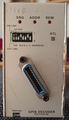
Front view of a late GPIB Decoder
-
-
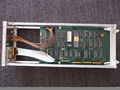
Left side of the GPIB decoder
-
Left side of the GPIB decoder closeup (late version)
-
-
-

-
-

-
-


Mounting Procedure
Location of electrical components
-
A late version of the 7A16P plugin is needed
-

Location of the connectors for the GPIB decoder on a 7A16P
-
Right side of a 7A29P plugin
-
Location of the connectors for the GPIB decoder on a 7A29P
-
A late version of the 7B90P plugin is needed
-

Location of the connectors for the GPIB decoder on a 7B90P
-
Location of the zener diode V330 on a late 7B90P
-
Location of the connectors to the plugins on the GPIB decoder


Mechanical components
-

Bracket for mounting the programmable plugins to the decoder
-

Bracket for mounting the programmable plugins to the decoder
-
Bracket for mounting the programmable plugins to the decoder
-
Bracket for mounting the programmable plugins to the decoder


Firmware (uploaded BIN files)
| Part number | Location | Used in |
|---|---|---|
| 160-3533-00.bin (?) | U4060 | up to #B010190 |
| 160-3533-01.bin (?) | U4060 | #B010191 and newer |