1A7: Difference between revisions
No edit summary |
Vintage dave (talk | contribs) (8393 not 7586) |
||
| Line 19: | Line 19: | ||
Maximum bandwidth is 500 kHz, and common-mode rejection is 50,000 to 1. | Maximum bandwidth is 500 kHz, and common-mode rejection is 50,000 to 1. | ||
Type 1A7's front end is a matched quad of [[ | Type 1A7's front end is a matched quad of [[8393]] [[nuvistor|nuvistors]], | ||
with two in parallel - to reduce noise - on each input. These tubes are | with two in parallel - to reduce noise - on each input. These tubes are | ||
in temperature-equalizing housings, and mounted on a rubber-isolated | in temperature-equalizing housings, and mounted on a rubber-isolated | ||
subchassis. The "coarse" balance adjustment controls the relative | subchassis. The "coarse" balance adjustment controls the relative | ||
heater voltages on the | heater voltages on the 8393's. | ||
Type 1A7 (initially named [[F|Type F]]) was designed by [[John Addis]] and [[introduced in 1966]]. | Type 1A7 (initially named [[F|Type F]]) was designed by [[John Addis]] and [[introduced in 1966]]. | ||
Revision as of 19:35, 4 April 2021
Template:Plugin Sidebar 2 The Tektronix Type 1A7 is a high-sensitivity differential plug-in for 500-series scopes. It senses down to 10 μV/Div, either AC or DC-coupled. It's possible to apply up to ± 300 mV offset to the reading while maintaining sensitivity. Upper and lower cutoff frequency is selectable on the front panel. Maximum bandwidth is 500 kHz, and common-mode rejection is 50,000 to 1.
Type 1A7's front end is a matched quad of 8393 nuvistors, with two in parallel - to reduce noise - on each input. These tubes are in temperature-equalizing housings, and mounted on a rubber-isolated subchassis. The "coarse" balance adjustment controls the relative heater voltages on the 8393's.
Type 1A7 (initially named Type F) was designed by John Addis and introduced in 1966.
Type 1A7A
In 1968, the 1A7 was superseded by the FET-equipped Type 1A7A (designed by Thor Hallen), which also doubled common-mode rejection and bandwidth (to 1 MHz).
The 1A7A's differential amplifier design was re-used with some modifications in the 3A9, 3A10, 7A22, 5A22N and 5030/5031 scopes. The AM502 and 26A2 use BJTs instead of JFETs for the offset current sources.
Type 1A7A remained available until the end of the 500-series line.
Key Specifications
| Deflection | 10 μV/Div to 10 V/Div in 1–2–5 sequence |
|---|---|
| Input impedance | 1 MΩ // 47 pF (either input) |
| — 1A7 — | |
| Bandwidth | 1 MHz, LF limit switchable DC, 0.1 Hz to 10 kHz in ×10 steps, HF limit switchable 100 Hz to 100 kHz in ×3/×10 steps, and 500 kHz; AC coupling 1.6 Hz |
| — 1A7A — | |
| Bandwidth | 1 MHz, LF limit switchable DC, 0.1 Hz to 10 kHz in ×10 steps, HF limit switchable 100 Hz to 1 MHz in ×3/×10 steps, AC coupling 1.6 Hz |
| Signal ranges |
| Range | Differential signal | DC Offset | Common mode |
|---|---|---|---|
| 10 μV/Div to 10 mV/Div | ±0.4 V | ±0.4 V | ±10 V |
| 20 mV/Div to 0.1 V/Div | ±4 V | ±4 V | ±100 V |
| 0.2 V/Div to 1 V/Div | ±40 V | ±40 V | ±500 V |
| 2 V/Div to 10 V/Div | ±400 V | ±400 V | ±500 V |
Pictures
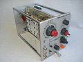
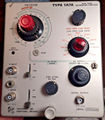
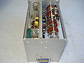
1A7


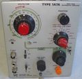
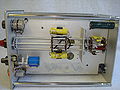
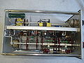
1A7A
-
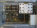
1A7A
-
1A7A
-
1A7A
-
1A7A
-
1A7A
-
1A7A
-
1A7A


