AFG5101: Difference between revisions
Jaredcabot (talk | contribs) (Added extra info.) |
Jaredcabot (talk | contribs) (Added extra LCD replacement info.) |
||
| Line 33: | Line 33: | ||
* [[Media:WaveWriter4 01E.zip|Wavewriter software Win3.1, 95, 98, NT4]] (ZIP) | * [[Media:WaveWriter4 01E.zip|Wavewriter software Win3.1, 95, 98, NT4]] (ZIP) | ||
* [[Media:AWGandAFGLabVIEWExamples.zip|Labview Examples]] (ZIP) | * [[Media:AWGandAFGLabVIEWExamples.zip|Labview Examples]] (ZIP) | ||
==Firmware== | ==Firmware== | ||
| Line 46: | Line 45: | ||
The backplane connectors use in this unit are DIN41612, or Eurocard connectors. The required extender cables can be easily made up using these connectors with ribbon cable to allow for adjustment and calibration. | The backplane connectors use in this unit are DIN41612, or Eurocard connectors. The required extender cables can be easily made up using these connectors with ribbon cable to allow for adjustment and calibration. | ||
==Repairs== | |||
The front display uses a blue electroluminescent panel for backlighting, which is usually almost completely faded and dim by now, and the LCD contrast is usually quite poor too.<br> | The front display uses a blue electroluminescent panel for backlighting, which is usually almost completely faded and dim by now, and the LCD contrast is usually quite poor too.<br> | ||
A standard cheap 5-volt Hitachi chipset compatible LCD module with 'parallel' interface can be used as a direct drop-in replacement | A standard cheap 5-volt Hitachi chipset compatible LCD module with 'parallel' interface can be used as a direct drop-in replacement with the removal of the EL inverter from the rear of the front panel PCB, and the LED backlight to be wired to the supply side of the now-removed EL inverter. Top pad is +ve (to anode). bottom pad is -ve (to cathode).<br> | ||
The new LCD may be 2mm thicker than the original LCD, this can be adjusted for by replacing the original 8mm tall brass standoffs with 6mm tall replacement standoffs.<br> | |||
If the contrast is too dark on the new LCD, the contrast pin (third from the left) on the header connector from the front panel PCB to the LCD PCB can be removed entirely, and the connection made with a 3.6 kΩ resistor around the edge of the PCB's. This (or a similar value) should bring the contrast back to center scale.<br> | |||
To adjust the contrast and turn the backlight on and off, press <SPCL>, then <2> <2> <0> followed by <ENTER>. The contrast can be adjusted using the up and down arrow keys and the backlight turned on and off using the <ENTER> key. | |||
The RAM backup battery is another common point of failure, this was originally a Renata 125-1 3-volt primary cell in a potted enclosure with two diodes. | The RAM backup battery is another common point of failure, this was originally a Renata 125-1 3-volt primary cell in a potted enclosure with two diodes. | ||
Revision as of 10:09, 21 September 2022

The Tektronix AFG5101 is a programmable arbitrary/function generator plug-in for the TM5000 system.
The plug-in is three compartments wide.
The AFG5501 is the same device in a mainframe of its own.
Key Specifications
| Frequency range | Sine, 0.012 Hz to 12 MHz; Arbitrary, Square, Ramp, Triangle, 0.001 Hz to 10 kHz |
|---|---|
| Duty cycle | 7% to 93% |
| Output | 10 mVp-p to 9.90 Vp-p (50 Ω), max. 19.98 Vp-p unloaded |
| Amplitude flatness | ±3 dB over full frequency range, ±0.5 dB from 0.012 Hz to 120 kHz |
| Distortion | ≤ 0.6% (≤ 1% for full temperature range) from 121 Hz to 120 kHz |
| Sweep | linear, logarithmic or arbitrary sweep |
Software
- SetFG Function Generator control software by Hakanh
- National Instruments Labview Drivers
- Wavewriter software Win3.1, 95, 98, NT4 (ZIP)
- Labview Examples (ZIP)
Firmware
- AFG5101 v1.2 Firmware 050-1201 (A1U105) (ZIP)
- AFG5101 v1.3 Firmware 050-1201 (A1U105) (ZIP)
- AFG5101 v1.4 Firmware 050-1201 (A1U105) (ZIP)
Options
- Option 02: Frequency locked synthesizer for enhanced frequency stability
Internals
The backplane connectors use in this unit are DIN41612, or Eurocard connectors. The required extender cables can be easily made up using these connectors with ribbon cable to allow for adjustment and calibration.
Repairs
The front display uses a blue electroluminescent panel for backlighting, which is usually almost completely faded and dim by now, and the LCD contrast is usually quite poor too.
A standard cheap 5-volt Hitachi chipset compatible LCD module with 'parallel' interface can be used as a direct drop-in replacement with the removal of the EL inverter from the rear of the front panel PCB, and the LED backlight to be wired to the supply side of the now-removed EL inverter. Top pad is +ve (to anode). bottom pad is -ve (to cathode).
The new LCD may be 2mm thicker than the original LCD, this can be adjusted for by replacing the original 8mm tall brass standoffs with 6mm tall replacement standoffs.
If the contrast is too dark on the new LCD, the contrast pin (third from the left) on the header connector from the front panel PCB to the LCD PCB can be removed entirely, and the connection made with a 3.6 kΩ resistor around the edge of the PCB's. This (or a similar value) should bring the contrast back to center scale.
To adjust the contrast and turn the backlight on and off, press <SPCL>, then <2> <2> <0> followed by <ENTER>. The contrast can be adjusted using the up and down arrow keys and the backlight turned on and off using the <ENTER> key.
The RAM backup battery is another common point of failure, this was originally a Renata 125-1 3-volt primary cell in a potted enclosure with two diodes.
A replacement can be replicated using a CR2032 cell and two 1N4148 diodes as used in the original part. See images below for the schematic of the original Renata part.
Pictures
-
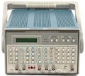
AFG5101 in Mainframe as AFG5501
-
-

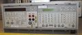
AFG5101 Front
-
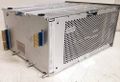
AFG5101 Rear
-

AFG5101 Right Side Internal
-
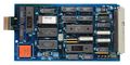
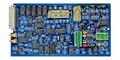
A1 CPU Circuit Board
-

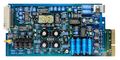
A2 ARB Circuit Board
-
A3 Analog Circuit Board
-
A4 Output Circuit Board
-
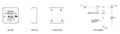
Schematic of Renata 125-1 RAM backup battery


